СИСТЕМА SFI, Diagnostic DTC:P0010, P0020
| DTC Code | DTC Name |
|---|---|
| P0010 | Camshaft Position "A" Actuator Circuit (Bank 1) |
| P0020 | Camshaft Position "A" Actuator Circuit (Bank 2) |
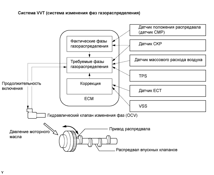
DESCRIPTION
This DTC is designed to detect opens or shorts in the camshaft oil control valve (OCV) circuit. If the OCV's duty-cycle is excessively high or low while the engine running, the ECM will illuminate the MIL and set the DTC.
The VVT (variable valve timing) system adjusts the intake valve timing to improve the driveability. The engine oil pressure turns the camshaft actuator to adjust the valve timing. The OCV is a solenoid valve and switches the engine oil line. The valve moves when the ECM applies the 12 volts to the solenoid. The ECM changes the energizing time to the solenoid (duty-cycle) in accordance with the camshaft position, crankshaft position, throttle position etc.
| DTC No. | DTC Detection Condition | Trouble Area |
|---|---|---|
| P0010 | Open or short in oil control valve circuit (bank 1) (1 trip detection logic) |
|
| P0020 | Open or short in oil control valve circuit (bank 2) (1 trip detection logic) |
|
MONITOR DESCRIPTION
After the ECM sends the "target" duty-cycle signal to the OCV, the ECM monitors the OCV current to establish an "actual" duty-cycle. The ECM detects a malfunction and sets a DTC when the actual duty-cycle ratio varies from the target duty-cycle ratio.
This monitor runs for 1 second (the first second of the engine idle) after the engine is started.
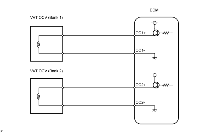
WIRING DIAGRAM
INSPECTION PROCEDURE
Tech Tips
-
If DTC P0010 is displayed, check the right bank VVT system circuit.
-
Bank 1 refers to the bank that includes the No. 1 cylinder.
-
If DTC P0020 is displayed, check the left bank VVT system circuit.
-
Bank 2 refers to the bank that does not include the No. 1 cylinder.
-
Read freeze frame data using the intelligent tester. Freeze frame data records the engine conditions when a malfunctions is detected. When troubleshooting, freeze frame data can help determine if the vehicle was running or stopped, if the engine was warmed up or not, if the air fuel ratio was lean or rich, and other data from the time the malfunction occurred.
PROCEDURE
-
CHECK DTC
-
Clear DTC after recording the freeze frame data and DTC.
-
Turn the ignition switch OFF.
-
Allow the engine to idle and check DTC.
-
Check that DTC P0010 is present.
OK P0010 is present.
NG 
CHECK FOR INTERMITTENT PROBLEMS
OK 
-
-
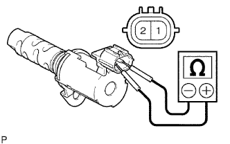
INSPECT CAMSHAFT TIMING OIL CONTROL VALVE ASSEMBLY
-
Disconnect the C18 and C19 OCV connectors.
-
Measure the resistance between the terminals of the OCV.
Standard resistance 6.9 to 7.9 Ω at 20°C (68°F) -
Reconnect the OCV connectors.
NG
REPLACE CAMSHAFT TIMING OIL CONTROL VALVE ASSEMBLY
OK
-
-
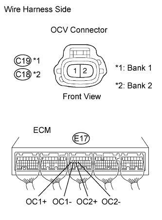
CHECK WIRE HARNESS (OCV - ECM)
-
Disconnect the C18 and C19 OCV connectors.
-
Disconnect the E17 ECM connector.
-
Measure the resistance.
standard (check for open) Tester Connection Specified Condition C19-1 - E17-17 (OC1+) Below 1 Ω C19-2 - E17-16 (OC1-) C18-1 - E17-15 (OC2+) C18-2 - E17-14 (OC2-) standard (check for short) Tester Connection Specified Condition C19-1 or E17-17 (OC1+) - Body ground 10 kΩ or higher C19-2 or E17-16 (OC1-) - Body ground C18-1 or E17-15 (OC2+) - Body ground C18-2 or E17-14 (OC2-) - Body ground -
Reconnect the OCV connectors.
-
Reconnect the ECM connector.
NG
REPAIR OR REPLACE HARNESS AND CONNECTOR
OK 
REPLACE ECM
-