FRONT BUMPER REASSEMBLY
-
INSTALL FRONT SIDE MEMBER BRACKET SUB-ASSEMBLY LH
-
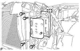
Engage the guide and install the front side member bracket sub-assembly LH.
-
Install the 4 bolts.
- Torque:
- 50 N*m { 510 kgf*cm, 37 ft.*lbf }
-
-
INSTALL FRONT SIDE MEMBER BRACKET SUB-ASSEMBLY RH
Tech Tips
Use the same procedure for the RH side and LH side.
-
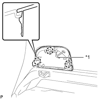
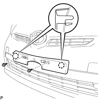
INSTALL FRONT BUMPER SIDE SUPPORT LH
-
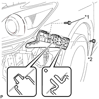
Text in Illustration *1 Bolt *2 Screw Engage the 2 claws to install the front bumper side support LH.
-
Install the bolt and screw.
- Torque:
- Bolt
- 5.4 N*m { 55 kgf*cm, 48 in.*lbf }
-
-
INSTALL FRONT BUMPER SIDE SUPPORT RH
Tech Tips
Use the same procedure for the RH side and LH side.
-
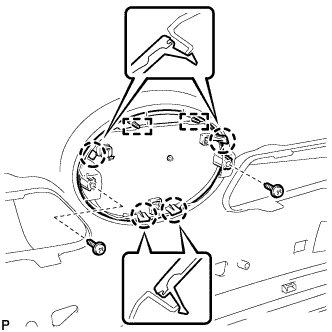
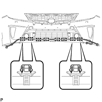
INSTALL FRONT BUMPER REINFORCEMENT SUB-ASSEMBLY
-
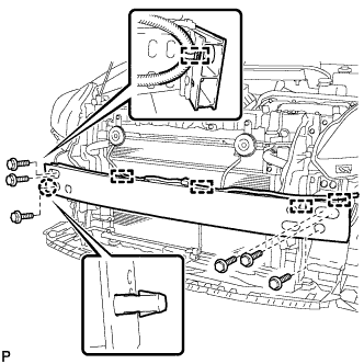
Engage the claw.
-
Install the front bumper reinforcement sub-assembly with the 6 bolts.
- Torque:
- 34 N*m { 347 kgf*cm, 25 ft.*lbf }
-
Engage the 5 clamps.
-
-
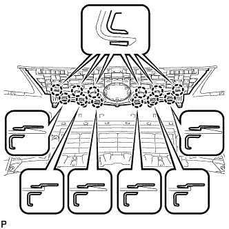
INSTALL FRONT BUMPER ENERGY ABSORBER
-
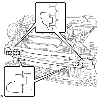
Engage the 4 guides to install the front bumper energy absorber.
-
-
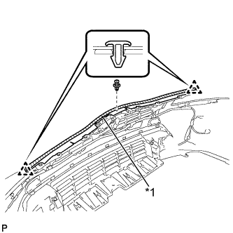
INSTALL FRONT BUMPER SEAL
-
Clean the front bumper reinforcement sub-assembly surface.
-
Remove the double-sided tape from the front bumper reinforcement sub-assembly.
-
Wipe off any tape adhesive residue with cleaner.
-
-
Remove the release paper from a new front bumper seal.
Tech Tips
After removing the release paper, keep the exposed adhesive free from foreign matter.
-
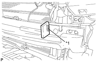
Text in Illustration *1 Double-sided Tape Install a new front bumper seal.
Tech Tips
Use the same procedure for the RH side and LH side.
-
-
INSTALL NO. 1 LOWER RADIATOR GRILLE
-
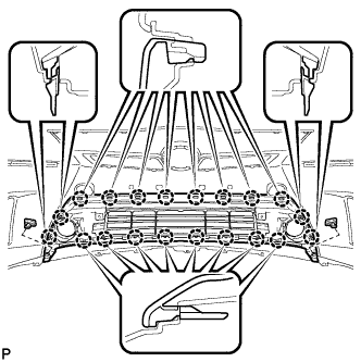
Engage the 20 claws to install the No. 1 lower radiator grille.
-
Install the 2 outside moulding retainers.
-
-
INSTALL NO. 2 LOWER RADIATOR GRILLE
-
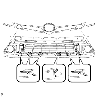
Engage the pin and 5 claws, to install the No. 2 lower radiator grille.
-
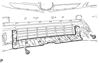
Install the 2 screws.
-
-
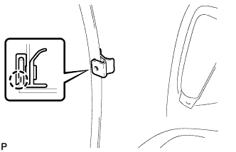
INSTALL FRONT BUMPER HOLE COVER LH
-
Text in Illustration *1 Hook Engage the hook.
-
Engage the 3 claws and install to front bumper hole cover LH.
-
-
INSTALL FRONT BUMPER HOLE COVER RH
Tech Tips
Use the same procedure for the RH side and LH side.
-
INSTALL FRONT FENDER LINER RETAINER
-
Engage the claw and install to front fender liner retainer.
Tech Tips
Use the same procedure for the RH side and LH side.
-
-
INSTALL RADIATOR GRILLE EMBLEM ASSEMBLY
-
Engage the 2 pins and 4 claws, to install the radiator grille emblem assembly.
-
Install the 2 screws.
- Torque:
- 3.0 N*m { 31 kgf*cm, 27 in.*lbf }
-
-
INSTALL RADIATOR GRILLE
-
Engage the 12 claws to install the radiator grille.
-
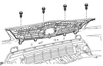
Install the 4 clips.
-
-
INSTALL HEADLIGHT CLEANER HOSE (w/ Headlight Cleaner System)
-
Engage the 8 clamps to install the headlight cleaner hose.
-
-
INSTALL ENGINE ROOM NO. 3 WIRE
-
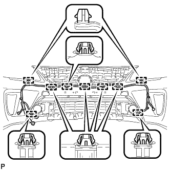
Engage the 9 clamps to install the engine room No. 3 wire.
-
-
INSTALL HOOD TO FRONT END PANEL SEAL
-
Clean the front bumper cover surface.
-
Remove the double-sided tape from the front bumper cover.
-
Wipe off any tape adhesive residue with cleaner.
-
-
Remove the release paper from a new hood to front end panel seal.
Tech Tips
After removing the release paper, keep the exposed adhesive free from foreign matter.
-
Text in Illustration *1 Double-sided Tape Engage the 2 clips and install a new hood to front end panel seal.
-
Install the clip.
-
-
INSTALL FRONT BUMPER EXTENSION MOUNTING BRACKET
-
Engage the 2 claws to install the front bumper extension mounting bracket.
-
Install the 2 screws.
-
-
INSTALL FOG LIGHT ASSEMBLY LH
-
Engage the 2 guides to temporarily install the fog light assembly.
-
Install the fog light assembly with the screw.
- Torque:
- 1.4 N*m { 14 kgf*cm, 12 in.*lbf }
-
Connect the connector.
-
-
INSTALL FOG LIGHT ASSEMBLY RH
Tech Tips
Use the same procedure for the RH side and LH side.
-
INSTALL FRONT TURN SIGNAL LIGHT ASSEMBLY LH (w/o Daytime Running Light)
-
Engage the 2 claws to temporarily install the front turn signal light assembly.
-
Install the front turn signal light assembly with the clip.
-
Engage each clamp.
-
Connect the connector.
-
-
INSTALL FRONT TURN SIGNAL LIGHT ASSEMBLY RH (w/o Daytime Running Light)
Tech Tips
Use the same procedure for the RH side and LH side.
-
INSTALL FRONT TURN SIGNAL LIGHT ASSEMBLY LH (w/ Daytime Running Light)
-
Engage the 2 claws to temporarily install the front turn signal light assembly.
-
Install the front turn signal light assembly with the clip.
-
Engage each clamp.
-
Connect the connector.
-
-
INSTALL FRONT TURN SIGNAL LIGHT ASSEMBLY RH (w/ Daytime Running Light)
Tech Tips
Use the same procedure for the RH side and LH side.
-
INSTALL NO. 1 ULTRASONIC SENSOR RETAINER (w/ Intelligent Parking Assist System)
-
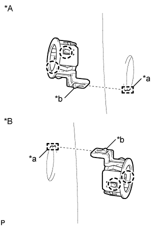
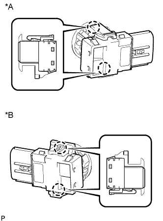
Text in Illustration *A RH Side *B LH Side *a Keyhole *b Snap Engage the 2 claws to install the No. 1 ultrasonic sensor retainer to the front bumper assembly.
Note
-
Do not damage the front bumper with the protrusion when installing the retainer.
-
Securely install the No. 1 ultrasonic sensor retainer so that there are no gaps between the retainer and surface of the front bumper.
Tech Tips
When installing the retainer, align the keyhole and snap as shown in the illustration.
-
-
-
INSTALL NO. 1 ULTRASONIC SENSOR (w/ Intelligent Parking Assist System)
-
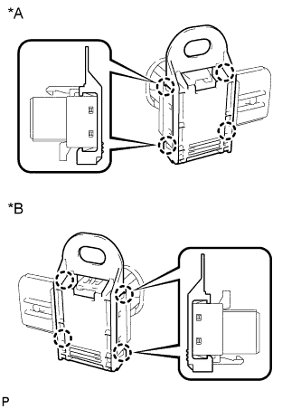
Text in Illustration *A RH Side *B LH Side Engage the 2 claws to install the No. 1 ultrasonic sensor to the No. 1 ultrasonic sensor retainer.
Note
Push the No. 1 ultrasonic sensor retainer from the outside of the bumper when there is a gap between the retainer and the bumper surface. In this case, do not push on the ultrasonic sensor.
-
-
INSTALL ULTRASONIC SENSOR CLIP (w/ Intelligent Parking Assist System)
-
Text in Illustration *A RH Side *B LH Side Engage the 4 claws to install the ultrasonic sensor clip.
-
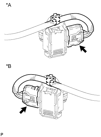
Text in Illustration *A RH Side *B LH Side Engage the clamp.
-
Connect the connector.
-
-
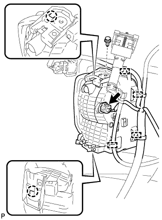
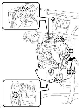
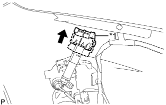
INSTALL HEADLIGHT WASHER ACTUATOR SUB-ASSEMBLY LH (w/ Headlight Cleaner System)
-
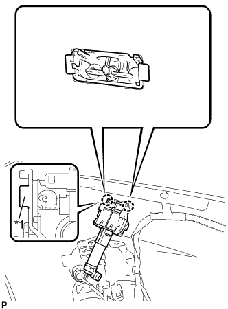
Text in Illustration *1 Tab Pushing the tab and engage the 2 claws to install the headlight washer actuator sub-assembly LH.
-
Text in Illustration *1 No. 1 Headlight Cleaner Clamp Push up the No. 1 headlight cleaner clamp.
-
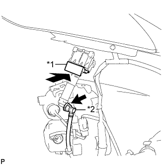
Text in Illustration *1 No. 3 Headlight Cleaner Clamp *2 Headlight Cleaner Hose Install the No. 3 headlight cleaner clamp.
-
Connect the headlight cleaner hose.
-
-
INSTALL HEADLIGHT WASHER ACTUATOR SUB-ASSEMBLY RH (w/ Headlight Cleaner System)
Tech Tips
Use the same procedure for the RH side and LH side.
-
INSTALL HEADLIGHT CLEANER WASHER NOZZLE COVER (w/ Headlight Cleaner System)
-
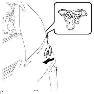
Engage the 2 claws to install the headlight cleaner washer nozzle cover.
Tech Tips
Use the same procedure for the RH side and LH side.
-