HAZARD WARNING SWITCH INSPECTION
-
INSPECT INTEGRATION CONTROL AND PANEL SUB-ASSEMBLY
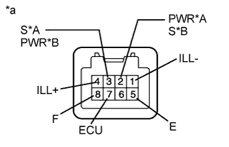
Text in Illustration *A for LHD *B for RHD *a Component without harness connected
(Integration Control and Panel Sub-assembly)
-
Hazard Warning Switch Inspection
-
Measure the resistance according to the value(s) in the table below.
Standard Resistance Tester Connection Condition Specified Condition 8 (F) - 5 (E) Hazard warning switch not pushed 10 kΩ or higher Hazard warning switch being pushed and held Below 1 Ω
-
-
ECO Mode Switch Inspection
-
Measure the resistance according to the value(s) in the table below.
Standard Resistance Tester Connection Condition Specified Condition 7 (ECU) - 5 (E) ECO mode switch not pushed 10 kΩ or higher ECO mode switch being pushed and held Below 1 Ω
-
-
EV/HV Mode Selection Switch Inspection (for LHD)
-
Measure the resistance according to the value(s) in the table below.
Standard Resistance Tester Connection Condition Specified Condition 3 (S) - 5 (E) EV/HV mode selection switch not pushed 10 kΩ or higher EV/HV mode selection switch being pushed and held Below 1 Ω
-
-
EV/HV Mode Selection Switch Inspection (for RHD)
-
Measure the resistance according to the value(s) in the table below.
Standard Resistance Tester Connection Condition Specified Condition 2 (S) - 5 (E) EV/HV mode selection switch not pushed 10 kΩ or higher EV/HV mode selection switch being pushed and held Below 1 Ω
-
-
EV City Mode Switch Inspection (for LHD)
-
Measure the resistance according to the value(s) in the table below.
Standard Resistance Tester Connection Condition Specified Condition 2 (PWR) - 5 (E) EV city mode switch not pushed 10 kΩ or higher EV city mode switch being pushed and held Below 1 Ω
-
-
EV City Mode Switch Inspection (for RHD)
-
Measure the resistance according to the value(s) in the table below.
Standard Resistance Tester Connection Condition Specified Condition 3 (PWR) - 5 (E) EV city mode switch not pushed 10 kΩ or higher EV city mode switch being pushed and held Below 1 Ω
-
-
Illumination Inspection
-
Apply auxiliary battery voltage to the headlight leveling switch and check that the switch illuminates.
OK Tester Connection Specified Condition Auxiliary battery positive (+) → Terminal 4 (ILL+)
Auxiliary battery negative (-) → Terminal 1 (ILL-)
Illuminates If the result is not as specified, replace the integration control and panel sub-assembly.
-
-