WIPER AND WASHER SYSTEM Headlight Cleaner Motor and Relay Circuit
DESCRIPTION
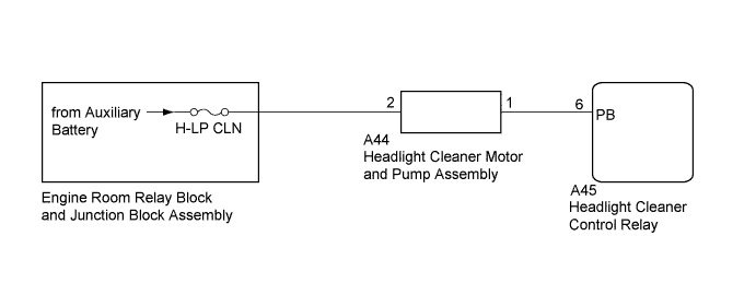
The headlight cleaner control relay controls the headlight cleaner motor and pump assembly.
WIRING DIAGRAM
INSPECTION PROCEDURE
Note
Inspect the fuses for circuits related to this system before performing the following inspection procedure.
PROCEDURE
-
INSPECT HEADLIGHT CLEANER MOTOR AND PUMP ASSEMBLY
Tech Tips
The following check should be performed with the headlight cleaner motor and pump assembly installed to the washer jar.
-
Fill the washer jar with washer fluid.
-
Disconnect the A44 headlight cleaner motor and pump assembly connector.
-
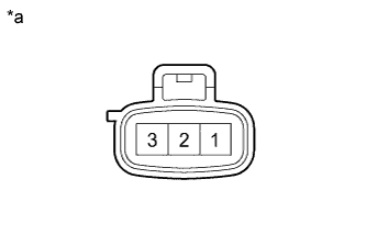
Text in Illustration *a Component without harness connected
(Headlight Cleaner Motor and Pump Assembly)
Connect an auxiliary battery positive (+) lead to terminal 2 of the headlight cleaner motor and pump assembly, and an auxiliary battery negative (-) lead to terminal 1.
-
Check that washer fluid flows from the washer jar.
OK Washer fluid is pumped from the washer jar.
NG 
REPLACE HEADLIGHT CLEANER MOTOR AND PUMP ASSEMBLY Click here
OK 
-
-
CHECK HARNESS AND CONNECTOR (HEADLIGHT CLEANER MOTOR CIRCUIT)
-
Connect the A44 headlight cleaner motor and pump assembly connector.
-
Disconnect the A45 headlight cleaner control relay connector.
-
Measure the voltage according to the value(s) in the table below.
Standard Voltage Tester Connection Condition Specified Condition A45-6 (PB) - Body ground Always 11 to 14 V
NG
REPAIR OR REPLACE HARNESS OR CONNECTOR
OK 
PROCEED TO NEXT SUSPECTED AREA SHOWN IN PROBLEM SYMPTOMS TABLE Click here
-