OUTER REAR VIEW MIRROR REASSEMBLY
Tech Tips
-
Use the same procedure for both the RH and LH sides.
-
The procedure described below is for the LH side.
-
INSTALL OUTER MIRROR RETRACTOR
-
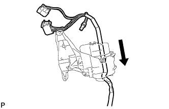
Pass a new wire harness through a new frame subassembly.
-
Connect the connector.
-
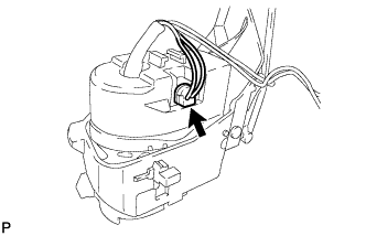
Temporarily install the frame sub-assembly with the guide as shown in the illustration.
-
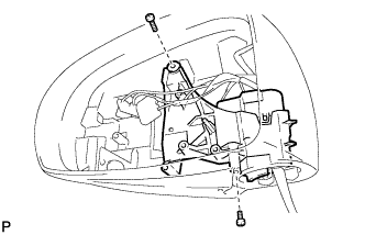
Install the frame sub-assembly with the 2 screws.
-
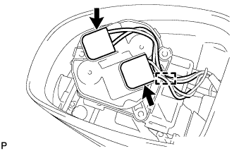
Connect the 2 connectors.
-
Engage the clamp.
-
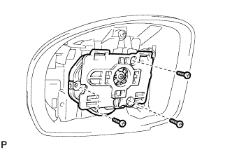
Install the mirror actuator with the 3 screws.
Note
When installing the mirror actuator, check that the wire harness is not caught.
-
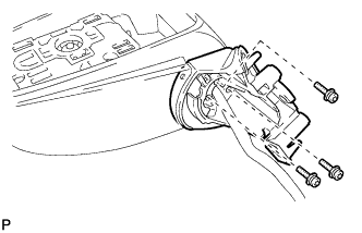
Using a T25 "TORX" socket wrench, install the base with 3 new screws.
- Torque:
- 3.8 N*m { 39 kgf*cm, 34 in.*lbf }
Note
When installing the base, check that the wire harness is not caught between the base and housing. Failure to do so may cause a short circuit.
-
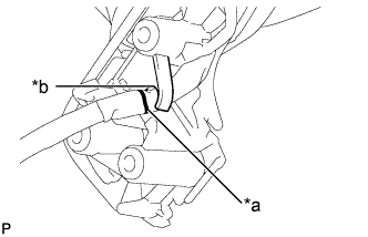
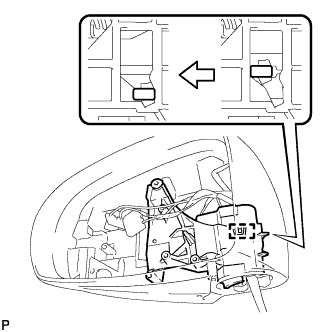
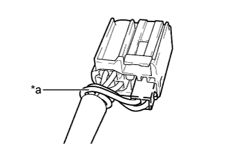
Text in Illustration *a Marking *b Position of the Clamp Set the marking of the wire harness to the position shown in the illustration to engage it.
-
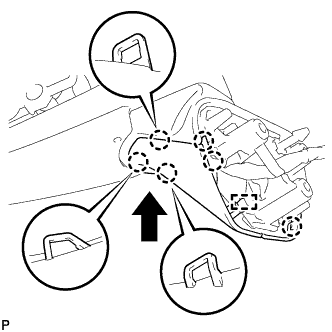
Engage the guide and 6 claws to install a new lower cover as shown in the illustration.
-
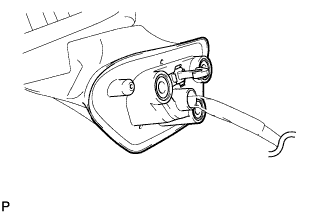
Pass the wire harness through a new gasket to install it.
-
Text in Illustration *a Twisted wire harness Install each connector to the adapter as shown in the illustration.
-
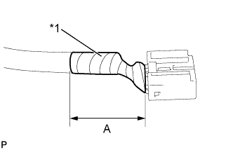
Text in Illustration *1 Vinyl Tape Wind vinyl tape around the wire harness to secure it.
Area Measurement A 40 mm (1.57 in.)
-
-
INSTALL SIDE TURN SIGNAL LIGHT ASSEMBLY
-
Install the side turn signal light assembly with the 3 screws.
-
Connect the connector.
-