FUEL LID LOCK CONTROL CABLE ASSEMBLY (for RHD) REMOVAL
-
REMOVE FRONT SEAT ASSEMBLY RH (for Manual Seat)
Tech Tips
Use the same procedure as for the LH side Click here.
-
REMOVE FRONT SEAT ASSEMBLY RH (for Power Seat)
-
REMOVE FRONT DOOR SCUFF PLATE RH
Tech Tips
Use the same procedure as for the LH side Click here.
-
REMOVE REAR DOOR SCUFF PLATE RH
Tech Tips
Use the same procedure as for the LH side Click here.
-
DISCONNECT FRONT DOOR OPENING TRIM WEATHERSTRIP RH
-
Disconnect the front door opening trim weatherstrip RH.
-
-
DISCONNECT REAR DOOR OPENING TRIM WEATHERSTRIP RH
-
Disconnect the rear door opening trim weatherstrip RH.
-
-
REMOVE REAR DOOR SCUFF PLATE LH
-
Disengage the 7 claws and remove the rear door scuff plate LH.
-
-
DISCONNECT REAR DOOR OPENING TRIM WEATHERSTRIP LH
-
Disconnect the rear door opening trim weatherstrip LH.
-
-
REMOVE LAP BELT OUTER ANCHOR COVER
Tech Tips
Use the same procedure as for the LH side Click here.
-
DISCONNECT FRONT SEAT OUTER BELT ASSEMBLY RH
Tech Tips
Use the same procedure as for the LH side Click here.
-
REMOVE CENTER PILLAR LOWER GARNISH RH
Tech Tips
Use the same procedure as for the LH side Click here.
-
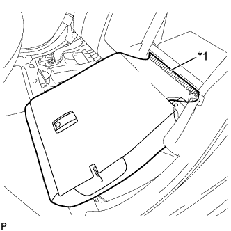
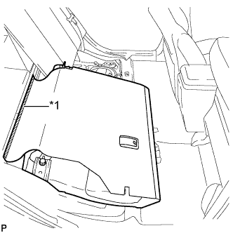
REMOVE REAR SEAT CUSHION ASSEMBLY
-
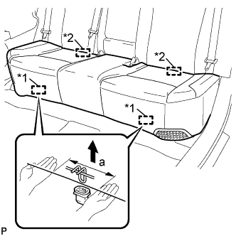
Text in Illustration *1 Front Hook *2 Rear Hook Disengage the front hook of the rear seat cushion assembly from the vehicle body as shown in the illustration.
Standard Measurement Dimension Measurement a 100 mm (3.94 in.) or less Note
Follow the instructions below carefully as the cushion frame can be deformed easily.
-
Choose a front hook to disengage first. Place your hands near the front hook as shown in the illustration. Then lift the seat cushion to disengage the front hook.
-
Repeat the above procedure for the other hook.
-
-
Disengage the 2 rear hooks of the rear seat cushion assembly from the rear seatback assembly.
-
Remove the rear seat cushion assembly.
Note
Be careful not to damage the vehicle body.
-
-
REMOVE REAR SIDE SEATBACK ASSEMBLY LH
-
Fold the rear seatback assembly LH forward.
-
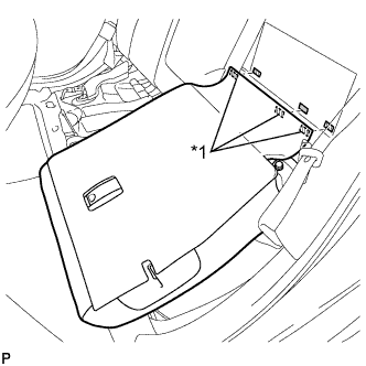
Text in Illustration *1 Fastener Disengage the 3 fasteners.
-

Remove the 2 bolts and rear seatback assembly LH.
Note
Be careful not to damage the vehicle body.
-
-
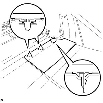
REMOVE REAR NO. 2 FLOOR BOARD
-
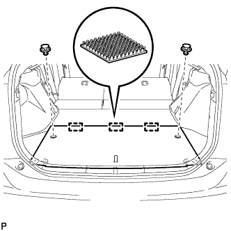
Using a clip remover, remove the 2 clips.
-
Disengage the 3 fasteners and remove the rear No. 2 floor board.
-
-
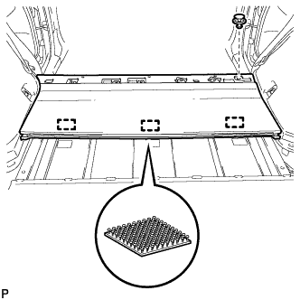
REMOVE TONNEAU COVER ASSEMBLY
-
Remove the tonneau cover assembly.
-
-
REMOVE REAR NO. 4 FLOOR BOARD SUB-ASSEMBLY
-
Remove the rear No.4 floor board sub-assembly.
-
-
REMOVE DECK FLOOR BOX LH
Tech Tips
Use the same procedure described for the RH side.
-
REMOVE REAR NO. 2 FLOOR BOARD SUB-ASSEMBLY
-
Disengage the claw and 2 clips, and remove the rear No. 2 floor board sub-assembly.
-
-
REMOVE REAR NO. 1 FLOOR BOARD SUB-ASSEMBLY
-
Disengage the claw and 3 clips, and remove the rear No. 1 floor board sub-assembly.
-
-
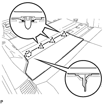
REMOVE REAR NO. 1 FLOOR BOARD
-
Fold the rear seatback assembly LH forward.
-
Text in Illustration *1 Fastener Disengage the fastener.
-
Fold the rear seatback assembly LH forward.
-
Text in Illustration *1 Fastener Disengage the fastener.
-
Using a clip remover, remove the clip.
-
Disengage the 3 fasteners and remove the rear No. 1 floor board.
-
-
REMOVE DECK TRIM SERVICE HOLE COVER
-
Disengage the 4 claws.
-
Disengage the 4 guides and remove the deck trim service hole cover.
-
-
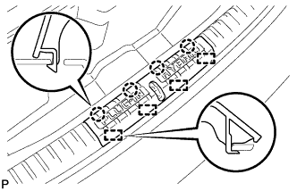
REMOVE REAR DECK TRIM COVER
-
Disengage the 4 claws and remove the rear deck trim cover.
-
-
REMOVE LUGGAGE HOLD BELT STRIKER ASSEMBLY (for LH Side)
-
Remove the 2 bolts.
-
Disengage each guide and remove the 2 luggage hold belt striker assemblies.
-
-
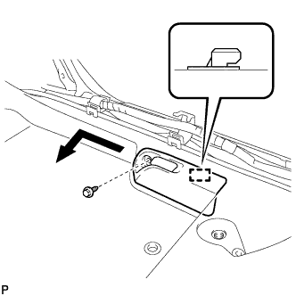
REMOVE TONNEAU COVER HOLDER CAP (for LH Side)
-
Text in Illustration *1 Protective Tape Using a screwdriver, disengage the claw and remove the tonneau cover holder cap.
Tech Tips
Tape the screwdriver tip before use.
-
-
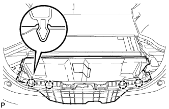
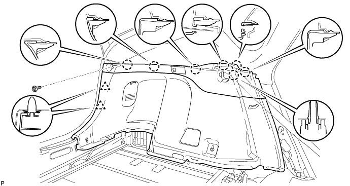
REMOVE DECK TRIM SIDE PANEL ASSEMBLY LH
-
Remove the screw.
-
Disengage the 7 claws and 2 clips.
-
Disconnect the connector and remove the deck trim side panel assembly LH.
-
-
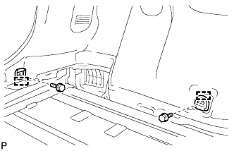
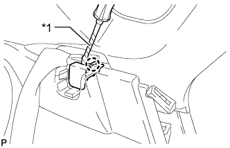
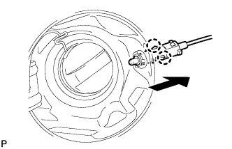
REMOVE FUEL LID LOCK OPEN LEVER SUB-ASSEMBLY
-
Remove the screw.
-
Disengage the guide and disconnect the fuel lid lock open lever sub-assembly as shown in the illustration.
-
Disconnect the fuel lid lock control cable sub-assembly.
-
-
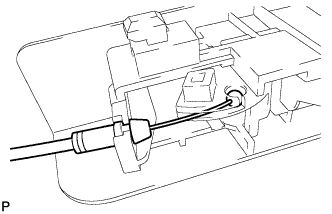
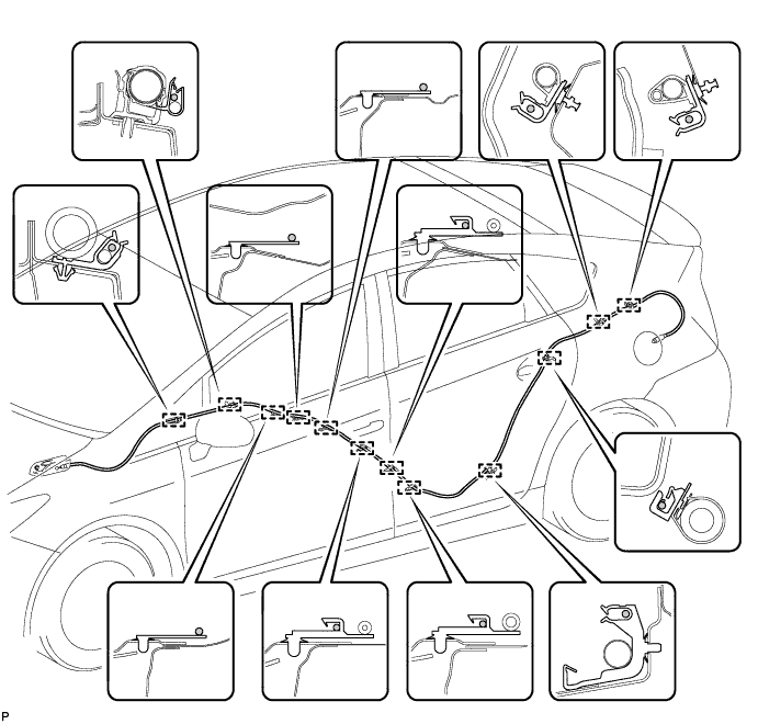
REMOVE FUEL LID LOCK CONTROL CABLE SUB-ASSEMBLY
-
Disengage the 2 claws and disconnect the fuel lid lock control cable sub-assembly.
-
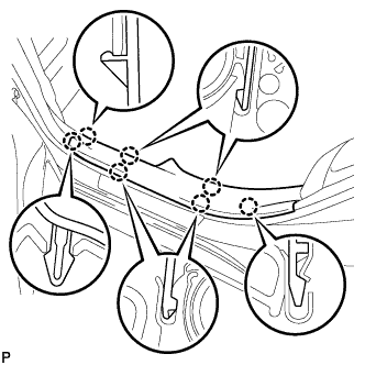
Disengage the 12 clamps and remove the fuel lid lock control cable sub-assembly.
-