BACK DOOR ADJUSTMENT
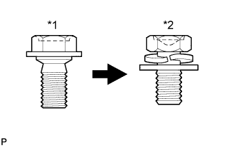
| *1 | Centering Bolt |
| *2 | Standard Bolt |
Tech Tips
-
Use the same procedure for the RH side and LH side.
-
The following procedure is for the LH side.
-
Centering bolts are used to mount the door hinge to the vehicle body and door. The door cannot be adjusted with the centering bolts installed. Substitute the centering bolts with standard bolts (with washers) when making adjustments.
-
Specified torque for standard bolts is shown in the standard bolt chart Click here.
-
INSPECT BACK DOOR
-
Check that the clearance measurements of areas "a" through "m" are within each standard range.
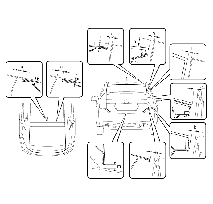
Standard Clearance Area Measurement Area Measurement a 5.7 to 8.7 mm (0.224 to 0.343 in.) b 0 to 3.0 mm (0 to 0.118 in.) c 5.7 to 8.7 mm (0.224 to 0.343 in.) d 0 to 3.0 mm (0 to 0.118 in.) e 3.2 to 6.2 mm (0.126 to 0.244 in.) f 3.6 to 6.6 mm (0.142 to 0.260 in.) g 2.85 to 6.85 mm (0.112 to 0.270 in.) h 9.65 to 13.65 mm (0.380 to 0.537 in.) i 2.85 to 6.85 mm (0.112 to 0.270 in.) j 4.0 to 8.0 mm (0.157 to 0.315 in.) k 4.5 to 8.5 mm (0.177 to 0.335 in.) l 3.85 to 7.85 mm (0.152 to 0.309 in.) m 4.35 to 7.35 mm (0.171 to 0.289 in.) - -
-
-
REMOVE REAR NO. 2 FLOOR BOARD
-
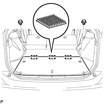
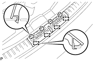
Using a clip remover, remove the 2 clips.
-
Disengage the 3 fasteners and remove the rear No. 2 floor board.
-
-
REMOVE REAR NO. 3 FLOOR BOARD
-
Remove the rear No. 3 floor board.
-
-
REMOVE DECK FLOOR BOX RH
-
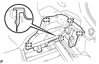
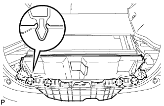
Disengage the claw and 4 guides and remove the deck floor box RH.
-
-
REMOVE REAR NO. 4 FLOOR BOARD SUB-ASSEMBLY
-
Remove the rear No.4 floor board sub-assembly.
-
-
REMOVE DECK FLOOR BOX LH
Tech Tips
Use the same procedure described for the RH side.
-
REMOVE DECK TRIM SERVICE HOLE COVER
-
Disengage the 4 claws.
-
Disengage the 4 guides and remove the deck trim service hole cover.
-
-
REMOVE REAR DECK TRIM COVER
-
Disengage the 4 claws and remove the rear deck trim cover.
-
-
ADJUST BACK DOOR
-
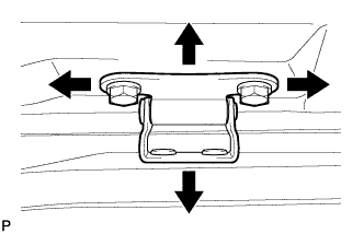
Before adjusting the upper end of the back door up and down or left and right, loosen the bolts.
-
Tighten the body side hinge after the adjustment.
- Torque:
- 19 N*m { 194 kgf*cm, 14 ft.*lbf }
-
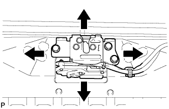
Loosen the 3 bolts.
-
Tighten the bolts after the adjustment.
- Torque:
- 7.5 N*m { 76 kgf*cm, 66 in.*lbf }
-

Text in Illustration *a Vehicle Body Side *b Door Side After adjusting the back door position, adjust the positions of the lower back door stopper and lower back door stopper cushion.
-
-
INSTALL REAR DECK TRIM COVER
-
Engage the 4 claws to install the rear deck trim cover.
-
-
INSTALL DECK TRIM SERVICE HOLE COVER
-
Engage the 4 guides.
-
Engage the 4 claws to install the deck trim service hole cover.
-
-
INSTALL DECK FLOOR BOX LH
Tech Tips
Use the same procedure described for the RH side.
-
INSTALL REAR NO. 4 FLOOR BOARD SUB-ASSEMBLY
-
Install the rear No. 4 floor board sub-assembly.
-
-
INSTALL DECK FLOOR BOX RH
-
Engage the claw and 4 guide to install the deck floor box RH.
-
-
INSTALL REAR NO. 3 FLOOR BOARD
-
Install the rear No. 3 floor board.
-
-
INSTALL REAR NO. 2 FLOOR BOARD
-
Engage the 3 fasteners.
-
Install the rear No. 2 floor board with the 2 clips.
-