LOWER INSTRUMENT PANEL REMOVAL
-
PRECAUTION
-
REMOVE UPPER INSTRUMENT PANEL ASSEMBLY
-
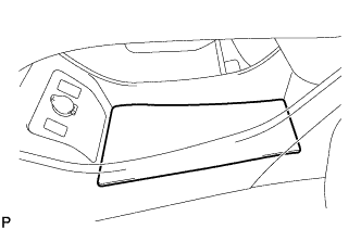
REMOVE REAR CONSOLE BOX CUP HOLDER
-
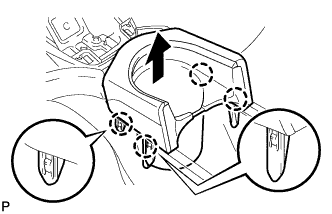
Disengage the 4 claws and remove the rear console box cup holder as shown in the illustration.
-
-
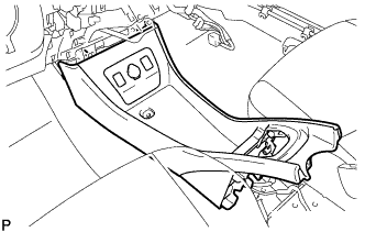
REMOVE CONSOLE BOX CARPET
-
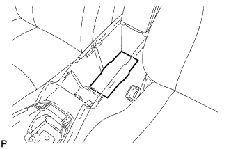
Remove the console box carpet.
-
-
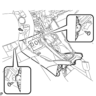
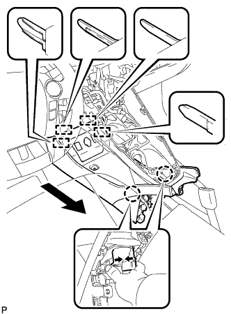
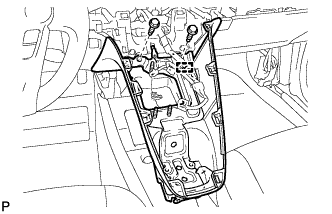
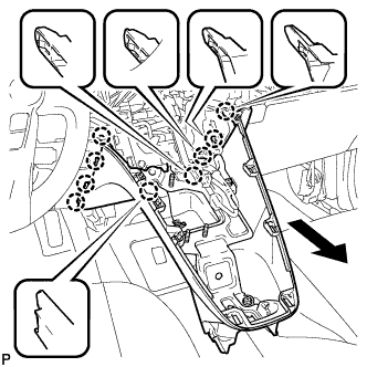
REMOVE REAR CONSOLE BOX ASSEMBLY
-
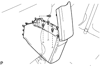
Remove the 5 bolts.
-
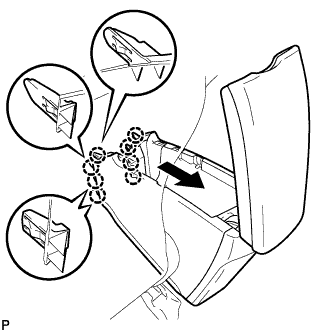
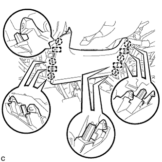
Pull the rear console box assembly in the direction indicated by the arrow to disengage the 8 claws.
-
Disconnect each connector and remove the rear console box assembly.
-
-
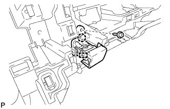
REMOVE NO. 1 INDOOR ELECTRICAL KEY ANTENNA ASSEMBLY
-
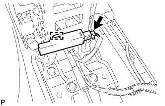
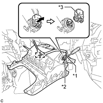
Disconnect the connector.
-
Disengage the clamp and remove the No. 1 indoor electrical key antenna assembly.
Note
Be careful when removing the No. 1 indoor electrical key antenna assembly. If the No. 1 indoor electrical key antenna assembly is dropped, replace it with a new one.
-
-
REMOVE NO. 2 CONSOLE BOX MOUNTING BRACKET
-
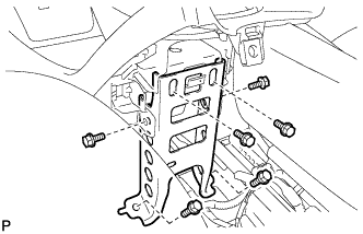
Remove the 6 bolts <B> and No. 2 console box mounting bracket.
-
-
REMOVE CONSOLE BOX INSERT
-
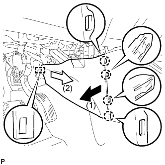
Pull the console box insert in the direction indicated by the arrow to disengage the 4 claws and guide, and remove the console box insert.
-
-
REMOVE FRONT NO. 2 CONSOLE BOX INSERT
-
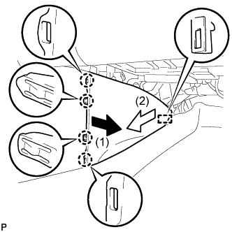
Pull the front No. 2 console box insert in the direction indicated by the arrow to disengage the 4 claws and guide, and remove the front No. 2 console box insert.
-
-
REMOVE BOX BOTTOM MAT
-
Remove the box bottom mat.
-
-
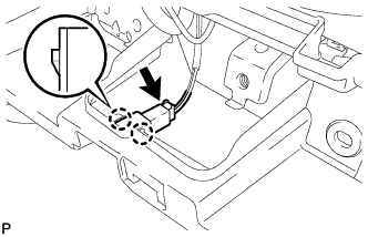
SEPARATE CONSOLE BOX ASSEMBLY
-
Remove the bolt <B> and 2 clips.
-
While pushing the parts shown in the illustration inward, pull the console box assembly in the direction indicated by the arrow to disengage the 2 claws and 4 guides.
-
Disconnect the connector and separate the console box assembly.
-
-
REMOVE AIR CONDITIONING CONTROL ASSEMBLY
-
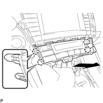
Disengage the 4 claws and remove the air conditioning control assembly as shown in the illustration.
-
Disconnect the connector.
-
-
REMOVE SHIFT LOCK CONTROL UNIT ASSEMBLY
-
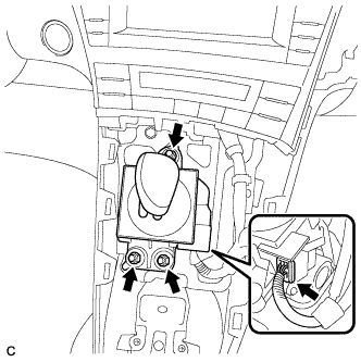
Disconnect the connector from the shift lock control unit assembly.
-
Remove the 3 nuts and shift lock control unit assembly.
-
-
REMOVE UPPER INSTRUMENT PANEL FINISH PANEL ASSEMBLY
-
Disengage the clamp.
-
Remove the 2 bolts <A>.
-
Pull the upper instrument panel finish panel assembly in the direction indicated by the arrow to disengage the 9 claws and remove the upper instrument panel finish panel assembly.
-
-
REMOVE CONSOLE BOX ASSEMBLY
-
Remove the console box assembly.
-
-
REMOVE NO. 1 SWITCH HOLE BASE
-
Disengage the 5 claws.
-
Disconnect the connector to remove the No. 1 switch hole base.
-
-
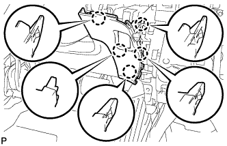
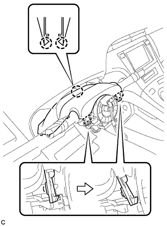
REMOVE LOWER STEERING COLUMN COVER
Note
Removing the lower steering column cover in the incorrect order will cause the parts to break.
-
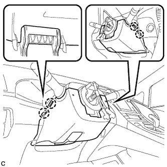
Push the right and left sides of the lower steering column cover to disengage the 4 claws.
-
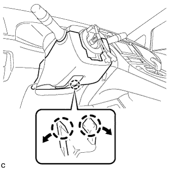
Insert fingers into the opening of the tilt lever of the lower steering column cover to disengage the 2 claws.
Tech Tips
Spread the claws to disengage them.
-
Using a screwdriver, insert the tip into each service hole to disengage the 2 claws to remove the lower steering column cover as shown in the illustration.
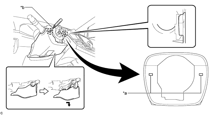
Text in Illustration *a Service Hole *b Protective Tape Tech Tips
Tape the screwdriver tip before use.
-
-
REMOVE UPPER STEERING COLUMN COVER
-
Disengage the 2 claws and 2 pins to remove the upper steering column cover.
-
-
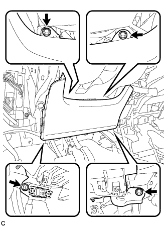
REMOVE NO. 1 INSTRUMENT PANEL UNDER COVER SUB-ASSEMBLY (for LHD)
-
Remove the 2 screws <D>.
-
Disengage the claw and guide.
-
Disconnect each connector and remove the No. 1 instrument panel under cover sub-assembly.
-
-
REMOVE NO. 1 INSTRUMENT PANEL UNDER COVER SUB-ASSEMBLY (for RHD)
-
Remove the screw <D>.
-
Disengage the 2 claws and guide.
-
Disconnect each connector and remove the No. 1 instrument panel under cover sub-assembly.
-
-
REMOVE LOWER NO. 1 INSTRUMENT PANEL AIRBAG ASSEMBLY
CAUTION:
When storing the lower No. 1 instrument panel airbag assembly, keep the airbag deployment side facing upward.
-
Check that the power switch is off.
-
Check that the cable is disconnected from the negative (-) auxiliary battery terminal.
CAUTION:
Wait at least 90 seconds after disconnecting the cable from the negative (-) auxiliary battery terminal to disable the SRS system.
-
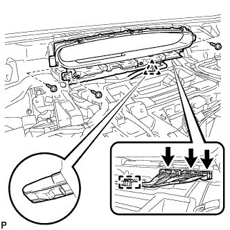
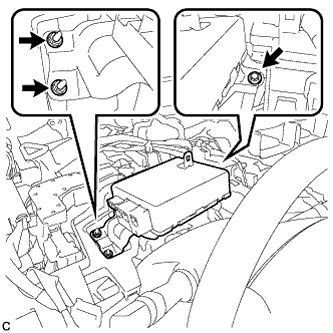
Remove the 4 bolts.
-
Disengage the 2 claws to disconnect the DLC3.
-
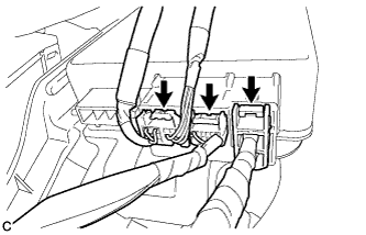
Disengage the 6 claws and 4 guides to separate the lower No. 1 instrument panel airbag assembly.
Note
When removing the lower No. 1 instrument panel airbag assembly, do not pull the airbag wire harness.
-
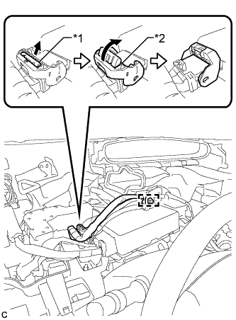
Text in Illustration *1 Protective Tape *2 Airbag Connector *3 Airbag Connector Lock Using a screwdriver with the tip wrapped with protective tape, release the airbag connector lock.
-
Disconnect the clamp and airbag connector to remove the lower No. 1 instrument panel airbag assembly.
Note
When disconnecting any airbag connector, take care not to damage the airbag wire harness.
-
-
REMOVE NO. 2 INSTRUMENT PANEL UNDER COVER SUB-ASSEMBLY
-
Disengage the 3 claws and guide.
-
Disconnect each connector and remove the No. 2 instrument panel under cover sub-assembly.
-
-
REMOVE GLOVE COMPARTMENT DOOR ASSEMBLY
-
for LHD:
-
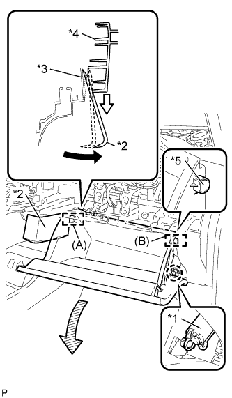
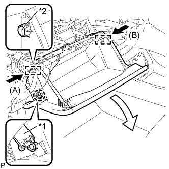
Text in Illustration *1 Glove Compartment Door Stopper Sub-assembly *2 Moulding Remover *3 Lower Instrument Panel Sub-assembly *4 Glove Compartment Door Assembly *5 Stopper Disengage the claw and release the glove compartment door stopper sub-assembly.
-
Insert the moulding remover into the location shown in the illustration.
-
Move the moulding remover in the direction indicated by the arrow to bend the lower instrument panel sub-assembly and release the stopper (A).
Tech Tips
Use the same procedure to release the stopper (B).
-
-
for RHD:
-
Text in Illustration *1 Glove Compartment Door Stopper Sub-assembly *2 Stopper Disengage the claw and release the glove compartment door stopper sub-assembly.
-
Slightly bend stoppers (A) and (B) in the directions indicated by the arrows in the illustration and pull the glove compartment door assembly until the stoppers are released.
-
-
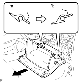
Text in Illustration *a Close *b Open Approximately Open the glove compartment door assembly to approximately 55° from its closed position. Pull it horizontally in the direction indicated by the arrow to disengage the 2 hinges and remove the glove compartment door assembly.
Note
Pulling the glove compartment door assembly upward to remove it causes the hinges to deform. Be sure to pull out the glove compartment door assembly horizontally.
-
-
REMOVE GLOVE COMPARTMENT DOOR STOPPER SUB-ASSEMBLY
-
Disengage the claw to remove the glove compartment door stopper sub-assembly.
-
-
REMOVE FRONT DOOR SCUFF PLATE RH
Tech Tips
Use the same procedure for the RH side and LH side Click here.
-
REMOVE COWL SIDE TRIM BOARD RH
Tech Tips
Use the same procedure for the RH side and LH side Click here.
-
REMOVE NO. 1 HEATER TO REGISTER DUCT
-
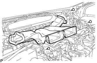
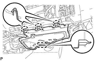
Remove the 3 clips and the No. 1 heater to register duct.
-
-
REMOVE COMBINATION METER ASSEMBLY
-
Disconnect the 3 connectors.
-
Disengage the clamp.
-
Remove the 3 screws.
-
Disengage the clip and remove the combination meter assembly.
-
-
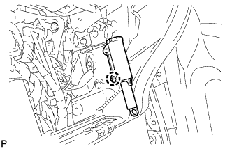
REMOVE POWER STEERING ECU ASSEMBLY
-
Text in Illustration *1 Lock of the Lock Lever *2 Lock Lever Disengage the wire harness clamp from the power steering ECU assembly.
-
Disconnect the connector from the power steering ECU assembly.
Tech Tips
As shown in the illustration, pull out the lock of the lock lever and turn the lock lever to disconnect the connector.
-
Disconnect the 3 connectors from the power steering ECU assembly.
-
Remove the bolt, 2 nuts and power steering ECU assembly.
-
-
REMOVE GLOVE COMPARTMENT DOOR LOCK ASSEMBLY
-
Remove the screw <D>.
-
Disengage the claw and guide, and remove the glove compartment door lock assembly.
-
-
REMOVE GLOVE BOX LIGHT ASSEMBLY
-
Disconnect the connector.
-
Using a screwdriver, disengage the 2 claws and remove the glove box light assembly.
-
-
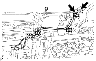
REMOVE ANTENNA CORD SUB-ASSEMBLY (for LHD)
-
for Plug Type Antenna Cord:
-
Disconnect the 2 connectors.
-
Remove the bolt.
-
Disengage the 4 clamps and remove the antenna cord sub-assembly.
-
-
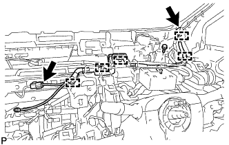
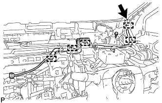
for Connector Type Antenna Cord:
-
Disconnect the connector.
-
Remove the bolt.
-
Disengage the 4 clamps and remove the antenna cord sub-assembly.
-
-
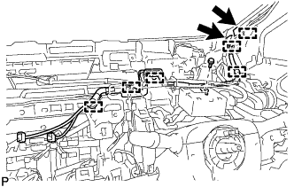
w/ Digital Audio Broadcasting Antenna:
-
Disconnect the 2connectors.
-
Remove the bolt.
-
Disengage the 5 clamps and remove the antenna cord sub-assembly.
-
-
-
REMOVE ANTENNA CORD SUB-ASSEMBLY (for RHD)
-
for Plug Type Antenna Cord:
-
Disconnect the 2 connectors.
-
Remove the bolt.
-
Disengage the 5 clamps and remove the antenna cord sub-assembly.
-
-
for Connector Type Antenna Cord:
-
Disconnect the connector.
-
Remove the bolt.
-
Disengage the 5 clamps and remove the antenna cord sub-assembly.
-
-
w/ Digital Audio Broadcasting Antenna:
-
Disconnect the 2connectors.
-
Remove the bolt.
-
Disengage the 6 clamps and remove the antenna cord sub-assembly.
-
-
-
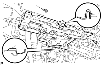
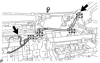
REMOVE LOWER INSTRUMENT PANEL SUB-ASSEMBLY (for LHD)
-
Disengage each clamp.
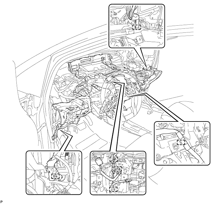
-
Remove the 4 bolts <B>, 11 bolts <C> and screw <D> and lower instrument panel sub-assembly.
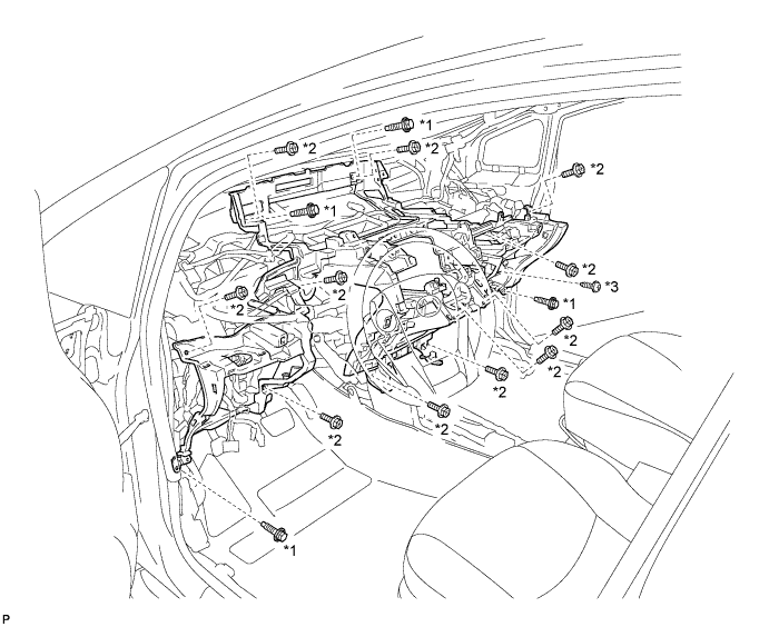
Text in Illustration *1 Bolt <B> *2 Bolt <C> *3 Screw <D> - -
-
-
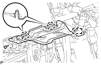
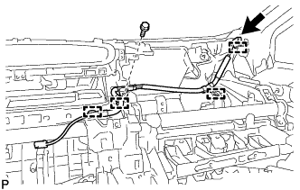
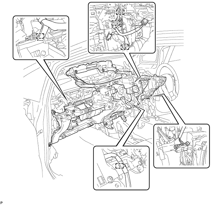
REMOVE LOWER INSTRUMENT PANEL SUB-ASSEMBLY (for RHD)
-
Disengage the 2 claws.
-
Disengage each clamp.
-
Remove the 4 bolts <B>, 11 bolts <C> and screw <D> and lower instrument panel sub-assembly.
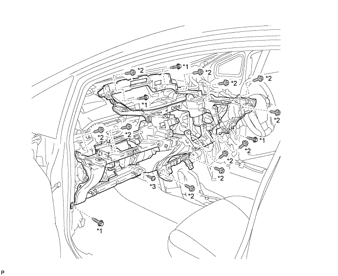
Text in Illustration *1 Bolt <B> *2 Bolt <C> *3 Screw <D> - -
-