ROOF HEADLINING REASSEMBLY
-
INSTALL NO. 1 ROOF WIRE
-
Apply double-sided tape as shown in the illustration.
-
Peel off the release paper from the double-sided tape.
-
Attach the No. 1 roof wire along the double-sided tape so that the marking surface of the wire harness faces downward.
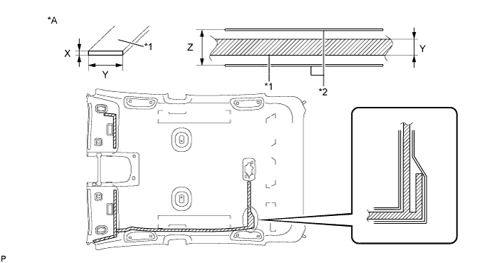
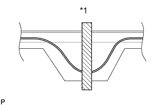
Text in Illustration *A Tape Attachment Locations (Reference) - - *1 Double-sided Tape *2 Marking Double-sided Tape Size X 1 mm (0.0394 in.) Y 10 mm (0.394 in.) Z 20 mm (0.787 in.) -
Align the pink marking tape <A> on the vehicle front side on the No. 1 roof wire with the vehicle front side tab on the roof headlining, and apply adhesive tape.
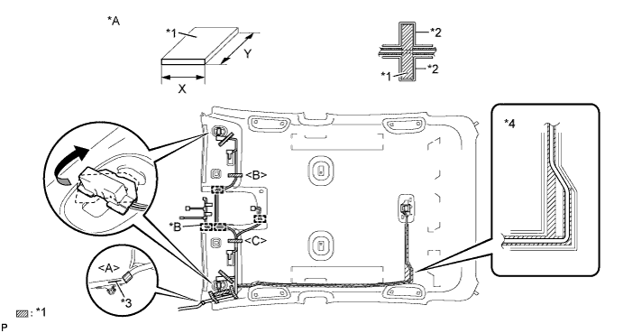
Text in Illustration *A Tape Attachment Locations (Reference) *B w/ Rain Sensor or w/ EC Mirror *1 Adhesive Tape *2 Marking *3 Marking Line (White) *4 Adjustment Area Tech Tips
Make sure that the No. 1 roof wire is not twisted and that the marking line (white) faces up.
-
Turn the visor connector RH clockwise approximately 45° to install the connector to the roof headlining assembly.
-
Align the pink marking tape <B> on the No. 1 roof wire with the markings on the roof headlining, and apply adhesive tape.
-
Engage each clamp.
-
Align the pink marking tape <C> on the No. 1 roof wire with the markings on the roof headlining, and apply adhesive tape.
-
Turn the visor connector LH clockwise approximately 45° to install the connector to the roof headlining assembly.
-
Attach the No. 1 roof wire, starting from the front of the vehicle, while aligning it with the double-side tape.
Note
-
Securely attach the No. 1 roof wire.
-
If any of the No. 1 roof wire is left loose, this will cause abnormal noise. Make sure to attach the No. 1 roof wire without leaving any loose.
Tech Tips
Secure the extra length of the No. 1 roof wire in the adjustment area.
-
-
Apply adhesive tape by aligning it with the markings on the roof headlining.
Adhesive Tape Size X 20 mm (0.787 in.) Y 100 mm (3.94 in.)
-
-
INSTALL NO. 2 ANTENNA CORD SUB-ASSEMBLY
Tech Tips
Double-sided tape and tape are not available as supply parts. If the tape still has enough adhesion to secure the roof headlining and antenna cord, reuse it. If the roof headlining has been replaced with a new one, or if the tape and/or the double-sided tape is no longer sticky, apply new tape following the procedure below.
If the double-sided tape cannot be reused:
-
Peel off the release paper from one side of new double-sided tape and apply the new double-sided tape to the position indicated in the illustration. Be careful not to touch the adhesive surface.
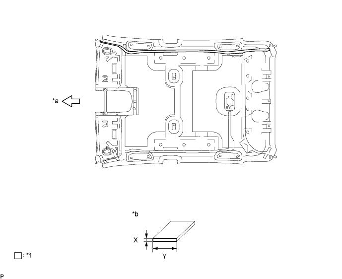
Text in Illustration *1 Double-sided Tape - - *a Front *b Double-sided Tape Size Double-sided Tape Size Area Dimension X 1.0 mm (0.0394 in.) Y 10.0 mm (0.394 in.) Note
Be sure to apply the double-sided tape carefully so that the tape will not be misaligned or come off.
-
Peel off the release paper from the double-sided tape. Be careful not to touch the adhesive surface.
-
Align the vehicle front side marking (pink) on the No. 2 antenna cord sub-assembly with the vehicle front side tab on the roof headlining, and wrap the tape over the antenna cord to install it. (1)
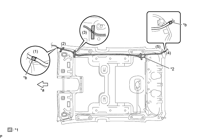
Text in Illustration *1 Tape *2 Extra Cord Storage Area *a Front *b Pink Tech Tips
If the tape cannot be reused, packing tape can be used as a substitute.
-
Temporarily install the front side of the No. 2 antenna cord sub-assembly with the adhesive tape. (2)
-
Temporarily install the front side of the No. 2 antenna cord sub-assembly with the adhesive tape. (3)
-
Temporarily install the No. 2 antenna cord sub-assembly by placing it on the double-sided tape from the front of the vehicle to the point just before the extra cord storage area.
-
Align the vehicle rear marking (pink) on the No. 2 antenna cord sub-assembly with the tape attachment location (scribe line) of the roof headlining, and wrap the tape over the antenna cord to install it. (4)
Tech Tips
If the tape cannot be reused, packing tape can be used as a substitute.
-
Temporarily install the No. 2 antenna cord sub-assembly by placing it on the double-sided tape from the rear of the vehicle to the point just before the extra cord storage area.
-
Text in Illustration *1 Extra Cord Storage Area Using tape, place any excess No. 2 antenna cord sub-assembly in the extra cord storage area to finish installing the antenna cord. (5)
-
-
INSTALL NO. 3 ROOF SILENCER PAD
-
Align the markings on the roof headlining assembly with the No. 3 roof silencer pad and install the set plate using hot-melt glue as shown in the illustration.
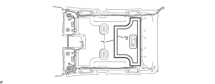
Text in Illustration *1 Roof Silencer Pad Marking *2 Hot-melt Glue Marking Note
Securely attach the No. 1 roof wire. Failure to do so may cause abnormal noise.
-
-
INSTALL NO. 2 ROOF SILENCER PAD
-
Align the markings on the roof headlining assembly with the No. 2 roof silencer pad and install the set plate using hot-melt glue as shown in the illustration.
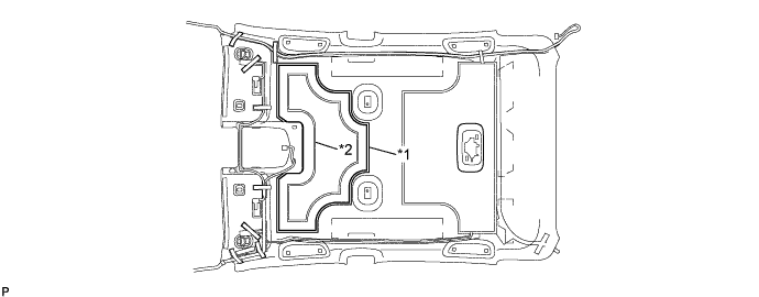
Text in Illustration *1 Roof Silencer Pad Marking *2 Hot-melt Glue Marking
-
-
INSTALL VANITY LIGHT ASSEMBLY
-
Install the vanity light assembly Click here.
Tech Tips
Use the same procedure for the other vanity light.
-