AIR CONDITIONING UNIT REMOVAL
-
PRECAUTION
Note
Make sure to select DEF mode before disconnecting the cable from the negative (-) auxiliary battery terminal.
-
RECOVER REFRIGERANT FROM AIR CONDITIONING SYSTEM
-
Start the hybrid system.
-
Operate the cooler compressor under the conditions show below:
Item Condition Engine Speed Idling Operating Time 3 minutes or more A/C Switch Status ON Blower Switch Status HI Set Temperature MAX COOL This causes most of the compressor oil from the various components of the A/C system to collect in the A/C compressor.
Tech Tips
There is no need to operate the cooler compressor if the A/C does not operate because of compressor lock, etc.
-
Stop the engine.
-
Recover the refrigerant from the A/C system using a refrigerant recovery unit.
Tech Tips
Use the refrigerant recovery unit in accordance with the manufacturer's instruction manual.
-
-
REMOVE WINDSHIELD WIPER MOTOR AND LINK ASSEMBLY
-
REMOVE COWL BODY MOUNTING REINFORCEMENT LH (for LHD)
-
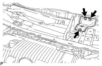
Remove the 3 bolts and cowl body mounting reinforcement LH.
-
-
REMOVE OUTER COWL TOP PANEL SUB-ASSEMBLY (for LHD)
-
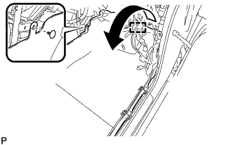
Disengage the clamp and separate the wire harness.
-
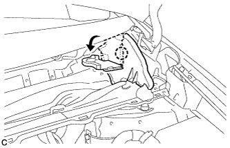
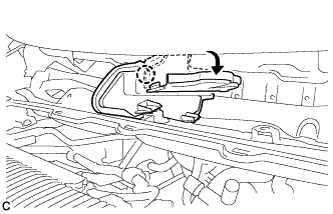
Disengage the claw and bend the No. 1 heater air duct splash shield seal.
-
Disengage the claw and bend the water guard plate RH.
-
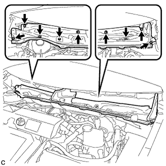
Remove the 9 bolts and outer cowl top panel sub-assembly.
-
-
REMOVE COWL BODY MOUNTING REINFORCEMENT RH (for RHD)
-
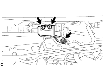
Remove the 3 bolts and cowl body mounting reinforcement RH.
-
-
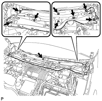
REMOVE OUTER COWL TOP PANEL SUB-ASSEMBLY (for RHD)
-
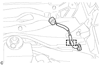
Disengage the clamp and separate the wire harness from the outer cowl top panel sub-assembly.
-
Disengage the clamp*1 and disconnect the connector (w/ Windshield Deicer).
-
Disengage the clamp*2 and separate the wire harness from the outer cowl top panel sub-assembly.
-
Disengage the claw and bend the No. 1 heater air duct splash shield seal.
-
Disengage the claw and bend the water guard plate RH.
-
Remove the 9 bolts and outer cowl top panel sub-assembly.
-
-
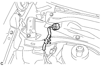
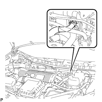
DISCONNECT SUCTION PIPE SUB-ASSEMBLY
-
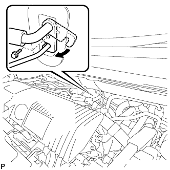
Remove the bolt and rotate the hook connector.
-
Disconnect the suction pipe sub-assembly.
-
Remove the O-ring from the suction pipe sub-assembly.
Note
Seal the openings of the disconnected parts using vinyl tape to prevent the entry of moisture and foreign matter.
-
-
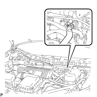
DISCONNECT AIR CONDITIONING TUBE AND ACCESSORY ASSEMBLY
-
Disconnect the air conditioning tube and accessory assembly.
-
Remove the O-ring from the air conditioning tube and accessory assembly.
Note
Seal the openings of the disconnected parts using vinyl tape to prevent the entry of moisture and foreign matter.
-
-
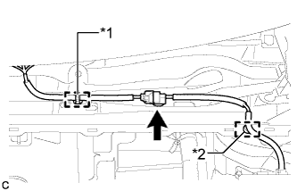
DISCONNECT INLET HEATER WATER HOSE
-
Using pliers, grip the claws of the clip and slide the clip to disconnect the inlet heater water hose.
Note
-
Do not apply excessive force to the inlet heater water hose.
-
Prepare a drain pan or cloth in case the coolant leaks.
-
-
-
DISCONNECT OUTLET HEATER WATER HOSE
-
Using pliers, grip the claws of the clip and slide the clip to disconnect the outlet heater water hose.
Note
-
Do not apply excessive force to the outlet heater water hose.
-
Prepare a drain pan or cloth in case the coolant leaks.
-
-
-
REMOVE LOWER INSTRUMENT PANEL SUB-ASSEMBLY
-
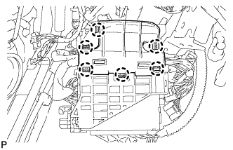
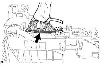
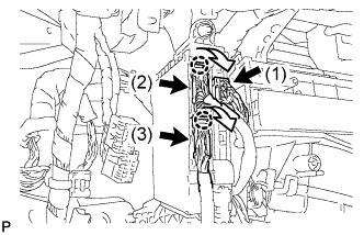
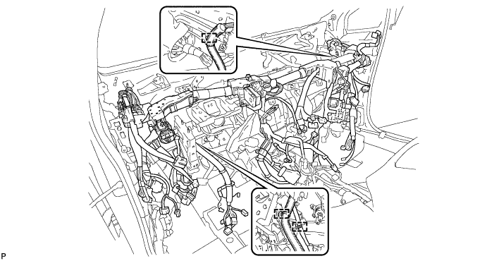
REMOVE INSTRUMENT PANEL JUNCTION BLOCK ASSEMBLY (for LHD)
-
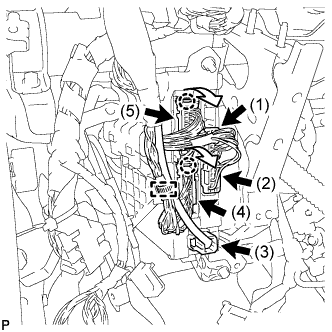
Disengage the clamp and disconnect the wire harness.
-
Disconnect the 3 connectors (1), (2) and (3).
-
Disengage the 2 claws and disconnect the 2 connectors (4) and (5) as shown in the illustration.
-
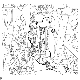
Remove the bolt and nut, and disconnect the instrument panel junction block assembly.
-
Disengage the 6 claws and remove the junction block bracket.
-
Disengage the 2 clamps and disconnect the wire harness.
-
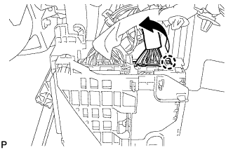
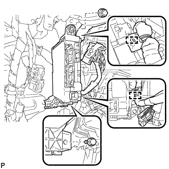
Disengage the claw and disconnect the connector as shown in the illustration.
-
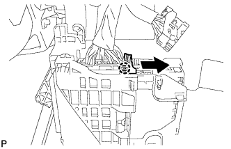
Disengage the claw and release the connector lock as shown in the illustration.
-
Disengage the claw and disconnect the connector as shown in the illustration.
-
Remove the instrument panel junction block assembly.
-
-
REMOVE ECU INTEGRATION BOX RH (for LHD)
-
Disconnect each connector.
-
Disengage the 3 clamps and disconnect the wire harness.
-
Remove the bolt, 2 nuts and ECU integration box.
-
-
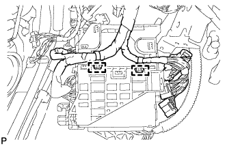
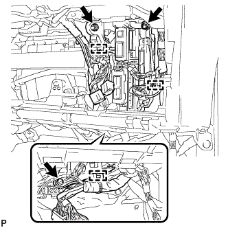
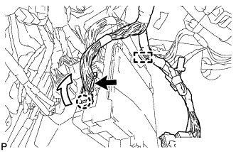
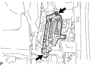
REMOVE INSTRUMENT PANEL JUNCTION BLOCK ASSEMBLY (for RHD)
-
Disconnect the connector (1).
-
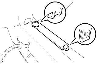
Disengage the 2 claws and disconnect the connector (2) and (3) as shown in the illustration.
-
Disengage the 2 clamps and disconnect the wire harness.
-
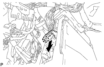
Remove the bolt and nut, and disconnect the instrument panel junction block assembly.
-
Disengage the clamp and disconnect the wire harness.
-
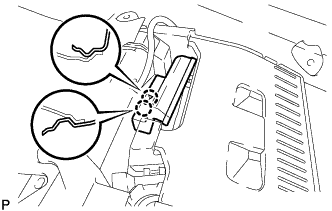
Disengage the claw and disconnect the connector as shown in the illustration.
-
Disengage the claw and release the connector lock as shown in the illustration.
-
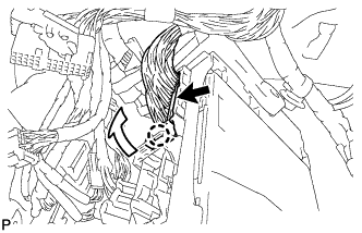
Disengage the claw and disconnect the connector as shown in the illustration.
-
Remove the instrument panel junction block assembly.
-
-
REMOVE ECU INTEGRATION BOX LH (for RHD)
-
Disconnect each connector.
-
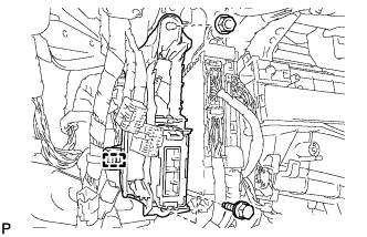
Disengage the clamp and disconnect the wire harness.
-
Remove the bolt, nut and ECU integration box.
-
-
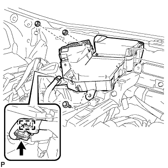
REMOVE ECU INTEGRATION BOX RH (for RHD)
-
for LHD:
-
Disconnect each connector.
-
Disengage the 3 clamps and disconnect the wire harness.
-
Remove the bolt, 2 nuts and ECU integration box RH.
-
-
for RHD:
-
Disconnect each connector.
-
Disengage the clamp and disconnect the wire harness.
-
Remove the bolt, nut and ECU integration box RH.
-
-
-
REMOVE HEADUP DISPLAY
-
Disconnect the connector.
-
Disengage the clamp.
-
Remove the bolt, 2 nuts and headup display.
-
-
REMOVE STEERING POST ASSEMBLY
-
REMOVE FRONT SEAT ASSEMBLY LH
for Manual Seat: Click here
for Power Seat: Click here
-
REMOVE FRONT SEAT ASSEMBLY RH
Tech Tips
Use the same procedure as for the LH side.
-
REMOVE FRONT FLOOR CAUTION PLATE COVER
-
Disengage the claw and guide, and remove the front floor caution plate cover.
-
-
REMOVE REAR NO. 4 AIR DUCT
-
Disengage the 2 claws and remove the rear No. 4 air duct.
-
-
REMOVE REAR NO. 2 AIR DUCT
-
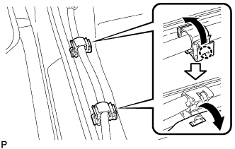
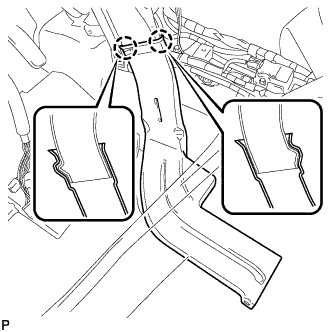
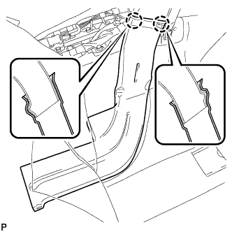
Disengage the 2 claws to open the 2 door scuff plate clamps and disconnect the floor carpet as shown in the illustration.
-
Remove the clip.
-
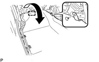
Disengage the fastener and turn back the floor carpet as shown in the illustration.
-
Disengage the 2 claws and remove the rear No. 2 air duct.
-
-
REMOVE REAR NO. 3 AIR DUCT
-
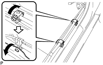
Disengage the 2 claws to open the 2 door scuff plate clamps and disconnect the floor carpet as shown in the illustration.
-
Remove the clip.
-
Disengage the fastener and turn back the floor carpet as shown in the illustration.
-
Disengage the 2 claws and remove the rear No. 3 air duct.
-
-
REMOVE REAR NO. 1 AIR DUCT
-
Disengage the 4 claws and remove the rear No. 1 air duct.
-
-
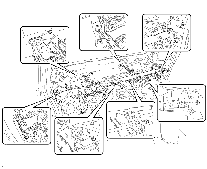
REMOVE NO. 1 INSTRUMENT PANEL BRACE SUB-ASSEMBLY
-
Disconnect the center airbag sensor connectors from the center airbag sensor assembly as shown in the illustration.
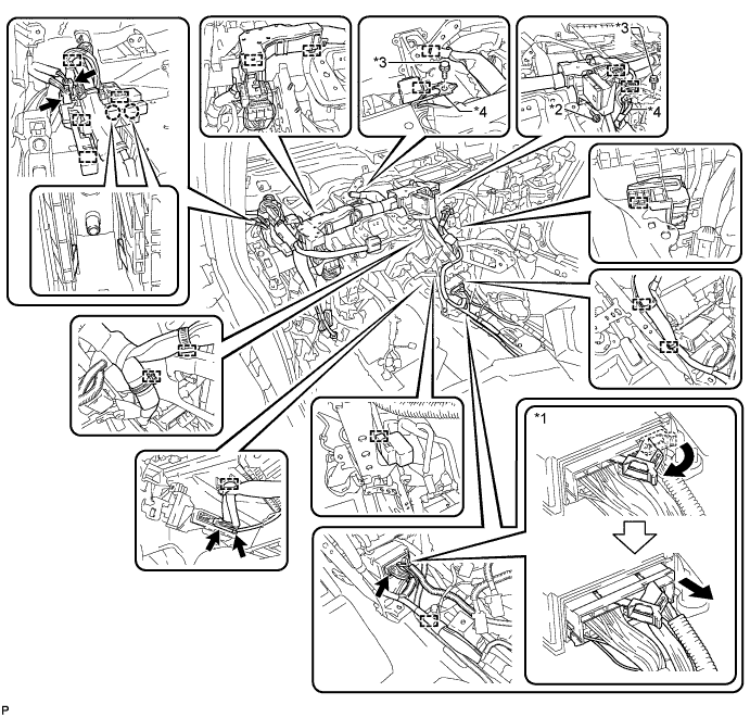
Text in Illustration *1 Center Airbag Sensor Connector *2 Screw *3 Bolt *4 Earth Wire Note
When disconnecting any airbag connector, take care not to damage the airbag wire harness.
-
Remove the screw.
-
Remove the 2 bolts and disconnect the 2 earth wires.
-
Disconnect each connector.
-
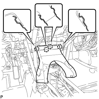
Disengage each clamp and claw.
-
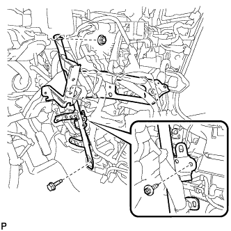
Remove the screw.
-
Remove the bolt, nut and No. 1 instrument panel brace sub-assembly.
-
-
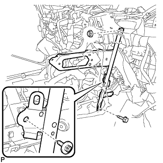
REMOVE NO. 2 INSTRUMENT PANEL BRACE SUB-ASSEMBLY
-
Remove the 3 screws.
Text in Illustration *1 Screw *2 Bolt *3 Earth Wire - - -
Remove the bolt and disconnect the earth wire.
-
Disconnect each connector.
-
Disengage each clamp.
-
Remove the screw.
-
Remove the bolt, nut and No. 2 instrument panel brace sub-assembly.
-
-
REMOVE NO. 3 SIDE DEFROSTER NOZZLE DUCT
-
Remove the clip and No. 3 side defroster nozzle duct.
-
-
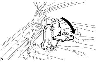
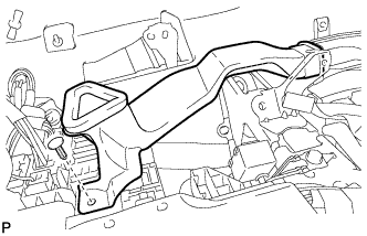
REMOVE DEFROSTER NOZZLE ASSEMBLY
-
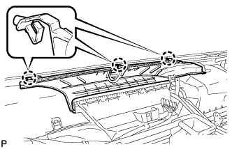
Disengage the 3 claws.
-
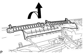
Remove the defroster nozzle assembly as shown in the illustration.
-
-
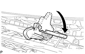
REMOVE LOWER DEFROSTER NOZZLE ASSEMBLY
-
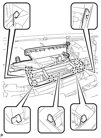
Disengage the clamp.
-
Disengage the 6 claws and remove the lower defroster nozzle assembly.
-
-
REMOVE NO. 3 AIR DUCT SUB-ASSEMBLY
-
Remove the 2 nuts and No. 3 air duct sub-assembly.
-
-
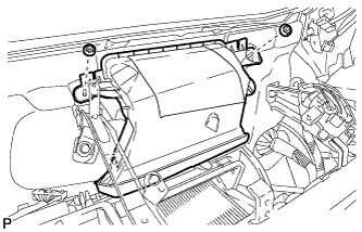
REMOVE INSTRUMENT PANEL REINFORCEMENT ASSEMBLY
-
Disengage each clamp.
-
Remove the 9 bolts and instrument panel reinforcement assembly.
-
-
REMOVE AIR CONDITIONING UNIT ASSEMBLY
Note
-
Be sure to support the air conditioning unit assembly when removing it because failure to do so may cause the bracket of the air conditioning unit assembly to break.
-
When disassembling the air conditioning unit assembly, eliminate static electricity by touching the vehicle body to prevent the components from being damaged.
-
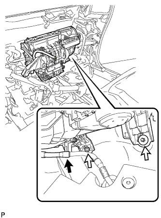
Disconnect the drain cooler hose.
-
Remove the bolt, nut and air conditioning unit assembly.
-
-
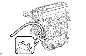
REMOVE BLOWER ASSEMBLY
-
w/ PTC Heater:
-
Remove the screw and disconnect the quick heater assembly connector.
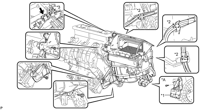
Text in Illustration *A w/ PTC Heater - - *1 Quick Heater Assembly Connector *2 Clamp *3 Guide - -
-
-
Disconnect the connector.
-
Disengage each clamp.
-
Remove the 3 screws.
-
Disengage the guide and remove the blower assembly.
-
-
REMOVE NO. 1 AIR DUCT SUB-ASSEMBLY
-
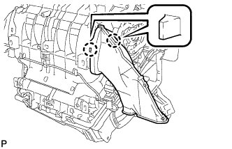
Disengage the 2 claws and remove the No. 1 air duct sub-assembly.
-
-
REMOVE AIR CONDITIONING DUCT SUB-ASSEMBLY
-
Disengage the 2 claws and remove the air conditioning duct sub-assembly.
-
-
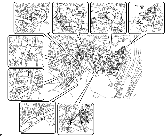
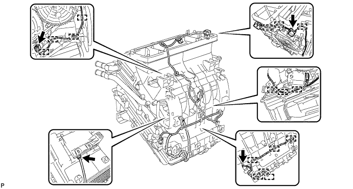
REMOVE AIR CONDITIONING HARNESS ASSEMBLY
-
Disconnect each connector.
-
Disengage each clamp and remove the air conditioning harness assembly.
-