AIR CONDITIONING SYSTEM ECO Switch Circuit
DESCRIPTION
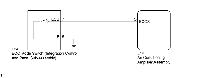
When the ECO mode switch (integration control and panel sub-assembly) is turned on, the air conditioning amplifier assembly receives an ECO mode switch (integration control and panel sub-assembly) ON signal and controls the air conditioning to enhance fuel efficiency.
WIRING DIAGRAM
INSPECTION PROCEDURE
PROCEDURE
-
READ VALUE USING GTS
-
Connect the GTS to the DLC3.
-
Turn the power switch on (IG).
-
Turn the GTS on.
-
Enter the following menus: Body Electrical / Air Conditioner / Data Test.
-
Check the values by referring to the table below.
Air Conditioner Tester Display Measurement Item/Range Control Range Diagnostic Note ECO Switch ECO mode switch (integration control and panel sub-assembly) /
OFF or ON
ECO mode switch (integration control and panel sub-assembly) being pushed and held: ON - ECO mode switch (integration control and panel sub-assembly) not pushed: OFF OK ECO mode switch (integration control and panel sub-assembly) condition displayed on the GTS changes with the actual switch operation.
NG 
INSPECT ECO MODE SWITCH (INTEGRATION CONTROL AND PANEL SUB-ASSEMBLY) Click here
OK 
PROCEED TO NEXT SUSPECTED AREA SHOWN IN PROBLEM SYMPTOMS TABLE Click here
-
-
INSPECT ECO MODE SWITCH (INTEGRATION CONTROL AND PANEL SUB-ASSEMBLY)
-
Remove the ECO mode switch (integration control and panel sub-assembly) Click here.
-
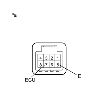
Text in Illustration *a Component without harness connected
(ECO Mode Switch (Integration Control and Panel Sub-assembly))
Measure the resistance according to the value(s) in the table below.
Standard Resistance Tester Connection Condition Specified Condition 7 (ECU) - 5 (E) ECO mode switch (integration control and panel sub-assembly) being pushed and held Below 1 Ω ECO mode switch (integration control and panel sub-assembly) not pushed 10 kΩ or higher
NG 
REPLACE ECO MODE SWITCH (INTEGRATION CONTROL AND PANEL SUB-ASSEMBLY) Click here
OK 
-
-
CHECK HARNESS AND CONNECTOR (ECO MODE SWITCH (INTEGRATION CONTROL AND PANEL) - AIR CONDITIONING AMPLIFIER ASSEMBLY)
-
Disconnect the L14 air conditioning amplifier assembly connector.
-
Measure the resistance according to the value(s) in the table below.
Standard Resistance Tester Connection Condition Specified Condition L14-9 (ECOS) - L64-7 (ECU) Always Below 1 Ω L14-9 (ECOS) - Body ground Always 10 kΩ or higher
NG
REPAIR OR REPLACE HARNESS OR CONNECTOR
OK
-
-
CHECK HARNESS AND CONNECTOR (ECO MODE SWITCH (INTEGRATION CONTROL AND PANEL SUB-ASSEMBLY) - BODY GROUND)
-
Measure the resistance according to the value(s) in the table below.
Standard Resistance Tester Connection Condition Specified Condition L64-5 (E) - Body ground Always Below 1 Ω
NG
REPAIR OR REPLACE HARNESS OR CONNECTOR
OK
REPLACE AIR CONDITIONING AMPLIFIER ASSEMBLY Click here
-