AIR CONDITIONING SYSTEM PTC Heater Circuit
DESCRIPTION
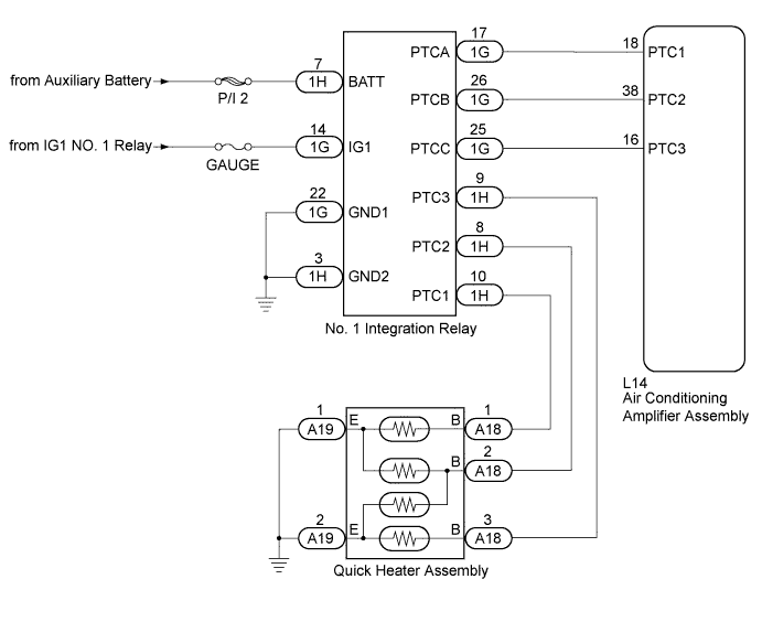
The air conditioning amplifier assembly sends operation signals to the No. 1 integration relay when the quick heater assembly (PTC heater) operation conditions are met. Based on the signals from the air conditioning amplifier assembly, the relays in the No. 1 integration relay turn on, and power is supplied to the quick heater assembly (PTC heater) installed in the air conditioning radiator assembly.
| Control ECU | Condition |
|---|---|
| Air Conditioning Amplifier Assembly | Blower motor on |
| Temperature set to MAX HOT | |
| ECO switch off | |
| IDH terminal signal less than 1 V (Inverter with converter assembly overload not detected) |
|
| Coolant temperature 55°C or lower | |
| Ambient temperature 10°C or lower |
WIRING DIAGRAM
INSPECTION PROCEDURE
Note
Inspect the fuses for circuits related to this system before performing the following inspection procedure.
PROCEDURE
-
PERFORM ACTIVE TEST USING GTS
-
Connect the GTS to the DLC3.
-
Turn the power switch on (IG).
-
Turn the GTS on.
-
Enter the following menus: Body Electrical / Air Conditioner / Active Test.
-
Check the operation by referring to the table below.
Air Conditioner Tester Display Test Part Control Range Diagnostic Note Heater Active Level Quick heater assembly Min.: 0, Max.: 3 - OK Heater Active Level changes normally.
NG 
INSPECT QUICK HEATER ASSEMBLY Click here
OK 
PROCEED TO NEXT SUSPECTED AREA SHOWN IN PROBLEM SYMPTOMS TABLE Click here
-
-
INSPECT QUICK HEATER ASSEMBLY
-
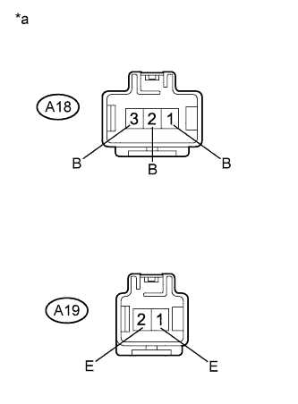
Text in Illustration *a Component without harness connected
(Quick Heater Assembly)
Remove the quick heater assembly Click here.
-
Measure the resistance according to the value(s) in the table below.
Standard Resistance Tester Connection Condition Specified Condition A18-3 (B) - A19-2 (E) Always Below 1 Ω A18-2 (B) - A19-2 (E) Always Below 1 Ω A18-2 (B) - A19-1 (E) Always Below 1 Ω A18-1 (B) - A19-1 (E) Always Below 1 Ω
NG 
REPLACE QUICK HEATER ASSEMBLY Click here
OK 
-
-
CHECK HARNESS AND CONNECTOR (QUICK HEATER ASSEMBLY - BODY GROUND)
-
Measure the resistance according to the value(s) in the table below.
Standard Resistance Tester Connection Condition Specified Condition A19-1 (E) - Body ground Always Below 1 Ω A19-2 (E) - Body ground Always Below 1 Ω
NG
REPAIR OR REPLACE HARNESS OR CONNECTOR
OK
-
-
CHECK HARNESS AND CONNECTOR (QUICK HEATER ASSEMBLY - NO. 1 INTEGRATION RELAY)
-
Disconnect the A18 quick heater assembly connector.
-
Disconnect the 1H No. 1 integration relay connector.
-
Measure the resistance according to the value(s) in the table below.
Standard Resistance Tester Connection Condition Specified Condition A18-1 (B) - 1H-10 (PTC1) Always Below 1 Ω A18-2 (B) - 1H-8 (PTC2) Always Below 1 Ω A18-3 (B) - 1H-9 (PTC3) Always Below 1 Ω A18-1 (B) - Body ground Always 10 kΩ or higher A18-2 (B) - Body ground Always 10 kΩ or higher A18-3 (B) - Body ground Always 10 kΩ or higher
NG
REPAIR OR REPLACE HARNESS OR CONNECTOR
OK
-
-
CHECK HARNESS AND CONNECTOR (NO. 1 INTEGRATION RELAY - POWER SOURCE)
-
Measure the voltage according to the value(s) in the table below.
Standard Voltage Tester Connection Condition Specified Condition 1G-14 (IG1) - Body ground Power switch off Below 1 V 1G-14 (IG1) - Body ground Power switch on (IG) 11 to 14 V 1H-7 (BATT) - Body ground Power switch off 11 to 14 V
NG
REPAIR OR REPLACE HARNESS OR CONNECTOR
OK
-
-
CHECK HARNESS AND CONNECTOR (NO. 1 INTEGRATION RELAY - BODY GROUND)
-
Disconnect the 1G No. 1 integration relay connector.
-
Measure the resistance according to the value(s) in the table below.
Standard Resistance Tester Connection Condition Specified Condition 1G-22 (GND1) - Body ground Always Below 1 Ω 1H-3 (GND2) - Body ground Always Below 1 Ω
NG
REPAIR OR REPLACE HARNESS OR CONNECTOR
OK
-
-
CHECK HARNESS AND CONNECTOR (AIR CONDITIONING AMPLIFIER - NO. 1 INTEGRATION RELAY)
-
Disconnect the L14 air conditioning amplifier assembly connector.
-
Measure the resistance according to the value(s) in the table below.
Standard Resistance Tester Connection Condition Specified Condition L14-18 (PTC1) - 1G-17 (PTCA) Always Below 1 Ω L14-38 (PTC2) - 1G-26 (PTCB) Always Below 1 Ω L14-16 (PTC3) - 1G-25 (PTCC) Always Below 1 Ω L14-18 (PTC1) - Body ground Always 10 kΩ or higher L14-38 (PTC2) - Body ground Always 10 kΩ or higher L14-16 (PTC3) - Body ground Always 10 kΩ or higher
NG
REPAIR OR REPLACE HARNESS OR CONNECTOR
OK
-
-
CHECK NO. 1 INTEGRATION RELAY
-
Replace the No. 1 integration relay Click here.
Tech Tips
Since the No. 1 integration relay cannot be inspected while it is removed from the vehicle, replace the No. 1 integration relay with a new or known good one and check that the condition returns to normal.
-
Check if the same problem occurs again.
OK Same problem does not occur.
NG
PROCEED TO NEXT SUSPECTED AREA SHOWN IN PROBLEM SYMPTOMS TABLE Click here
OK
END (NO. 1 INTEGRATION RELAY WAS DEFECTIVE)
-