AIR CONDITIONING SYSTEM TERMINALS OF ECU
-
AIR CONDITIONING AMPLIFIER ASSEMBLY
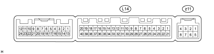
Tech Tips
Check from the rear of the connector while it is connected to the air conditioning amplifier assembly.
Terminal No.
(Symbol)
Wiring Color Terminal Description Condition Specified Condition L14-1 (IG+) - L14-14 (GND) B - W-B Power source (IG) Power switch on (IG) 11 to 14 V L14-1 (IG+) - L14-14 (GND) B - W-B Power source (IG) Power switch off Below 1 V L14-5 (TAM) - L14-13 (SG-2) BE - G Ambient temperature sensor signal Power switch on (IG)
Ambient temperature: 25°C (77°F)
1.35 to 1.75 V L14-5 (TAM) - L14-13 (SG-2) BE - G Ambient temperature sensor signal Power switch on (IG)
Ambient temperature: 40°C (104°F)
0.9 to 1.2 V L14-9 (ECOS) - L14-14 (GND) G - W-B Eco mode switch signal Power switch on (IG)
ECO mode switch (integration control and panel sub-assembly) not pushed
11 to 14 V L14-9 (ECOS) - L14-14 (GND) G - W-B Eco mode switch signal Power switch on (IG)
ECO mode switch (integration control and panel sub-assembly) being pushed and held
Below 1 V L14-10 (S5-3) - L14-13 (SG-2) B - G Power supply for air conditioning pressure sensor Power switch on (IG) 4.75 to 5.25 V L14-10 (S5-3) - L14-13 (SG-2) B - G Power supply for air conditioning pressure sensor Power switch off Below 1 V L14-11 (CANH) - L14-12 (CANL) Y - BR CAN communication system CAN communication occurring Pulse generation L14-13 (SG-2) - Body ground G - Body ground Ground for air conditioning pressure sensor, ambient temperature sensor Always Below 1 V L14-14 (GND) - Body ground W-B - Body ground Ground for main power supply Always Below 1 V L14-16 (PTC3) - L14-14 (GND)*1 BR - W-B PTC heater operation signal
-
Power switch on (READY)
-
Temperature setting: MAX HOT
-
Ambient temperature: 10°C (50°F) or lower
-
Engine coolant temperature: 55°C (131°F) or lower
-
Eco mode switch off
-
Blower switch on
Below 1 V L14-16 (PTC3) - L14-14 (GND)*1 BR - W-B PTC heater operation signal
-
Power switch on (READY)
-
Temperature setting: MAX HOT
-
Ambient temperature: 10°C (50°F) or lower
-
Engine coolant temperature: 55°C (131°F) or lower
-
Eco mode switch on
-
Blower switch off
11 to 14 V L14-18 (PTC1) - L14-14 (GND)*1 W - W-B PTC heater operation signal
-
Power switch on (READY)
-
Temperature setting: MAX HOT
-
Ambient temperature: 10°C (50°F) or lower
-
Engine coolant temperature: 55°C (131°F) or lower
-
Eco mode switch off
-
Blower switch on
Below 1 V L14-18 (PTC1) - L14-14 (GND)*1 W - W-B PTC heater operation signal
-
Power switch on (READY)
-
Temperature setting: MAX HOT
-
Ambient temperature: 10°C (50°F) or lower
-
Engine coolant temperature: 55°C (131°F) or lower
-
Eco mode switch on
-
Blower switch off
11 to 14 V L14-21 (B) - L14-14 (GND) Y - W-B Power source (Back-up) Power switch off 11 to 14 V L14-23 (BLW) - L14-14 (GND) W - W-B Blower motor speed control signal Power switch on (IG)
Blower switch LO
Pulse generation
(See waveform 1)
L14-27 (IDH) - L14-14 (GND)*1 L - W-B Inverter with converter assembly current over signal Power switch on (IG)
Quick heater assembly operation not permitted
4.5 to 5.5 V L14-27 (IDH) - L14-14 (GND)*1 L - W-B Inverter with converter assembly current over signal Power switch on (IG)
Quick heater assembly operation permitted
Less than 1 V L14-29 (TR) - L14-34 (SG-1) B - W Room temperature sensor signal Power switch on (IG)
Cabin temperature: 25°C (77°F)
1.8 to 2.2 V L14-29 (TR) - L14-34 (SG-1) B - W Room temperature sensor signal Power switch on (IG)
Cabin temperature: 40°C (104°F)
1.2 to 1.6 V L14-32 (PRE) - L14-13 (SG-2) L - G Air conditioning pressure sensor signal
-
Power switch on (READY)
-
A/C system operating
-
Refrigerant pressure: Abnormal pressure (more than 3140 kPa (32.0 kgf/cm2, 455 psi))
4.88 V or higher L14-32 (PRE) - L14-13 (SG-2) L - G Air conditioning pressure sensor signal
-
Power switch on (READY)
-
A/C system operating
-
Refrigerant pressure: Abnormal pressure (less than 196 kPa (2.0 kgf/cm2, 28 psi))
Below 0.66 V L14-32 (PRE) - L14-13 (SG-2) L - G Air conditioning pressure sensor signal
-
Power switch on (READY)
-
A/C system operating
-
Refrigerant pressure: Normal pressure (less than 3140 kPa (32.0 kgf/cm2, 455 psi) and more than 196 kPa (2.0 kgf/cm2, 28 psi))
0.66 to 4.88 V L14-33 (TS) - L14-14 (GND) BR - W-B Solar sensor signal Power switch on (IG)
Solar sensor subjected to electric light
0.8 to 4.3 V L14-33 (TS) - L14-14 (GND) BR - W-B Solar sensor signal Power switch on (IG)
Solar sensor covered with a cloth
Below 0.8 V L14-34 (SG-1) - Body ground W - Body ground Ground for room temperature sensor Always Below 1 V L14-37 (LIN1) - L14-14 (GND) V - W-B LIN communication signal Power switch on (IG) Pulse generation L14-38 (PTC2) - L14-14 (GND)*1 B - W-B PTC heater operation signal
-
Power switch on (READY)
-
Temperature setting: MAX HOT
-
Ambient temperature: 10°C (50°F) or lower
-
Engine coolant temperature: 55°C (131°F) or lower
-
Eco mode switch off
-
Blower switch on
Below 1 V L14-38 (PTC2) - L14-14 (GND)*1 B - W-B PTC heater operation signal
-
Power switch on (READY)
-
Temperature setting: MAX HOT
-
Ambient temperature: 10°C (50°F) or lower
-
Engine coolant temperature: 55°C (131°F) or lower
-
Eco mode switch on
-
Blower switch off
11 to 14 V z11-2 (BUS G) - Body ground - Ground for BUS IC Always Below 1 V z11-4 (B BUS) - z11-2 (BUS G) - Power supply for BUS IC Power switch off 11 to 14 V z11-5 (SGA) - Body ground - Ground for evaporator temperature sensor Always Below 1 V z11-6 (TEA) - z11-5 (SGA) - Evaporator temperature sensor signal Power switch on (IG)
Evaporator temperature: 0°C (32°F)
1.7 to 2.1 V z11-6 (TEA) - z11-5 (SGA) - Evaporator temperature sensor signal Power switch on (IG)
Evaporator temperature: 15°C (59°F)
0.9 to 1.3 V
-
*1: w/ Quick Heater Assembly
-
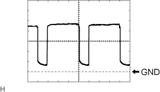
Waveform 1:
Item Content Terminal No. L14-23 (BLW) - L14-14 (GND) Tool Setting 1 V/DIV., 500 μs/DIV. Vehicle Condition Power switch on (IG)
Blower switch LO
Tech Tips
The waveform varies with the blower speed.
-
-
POWER MANAGEMENT CONTROL ECU Click here
-
AIR CONDITIONING CONTROL ASSEMBLY

Tech Tips
Check from the rear of the connector while it is connected to the air conditioning control assembly.
Terminal No.
(Symbol)
Wiring Color Terminal Description Condition Specified Condition L17-2 (TX+) - L17-8 (GND) V - W-B LIN communication signal Power switch on (IG) Pulse generation L17-3 (SWO) - L17-8 (GND) L - W-B Steering pad switch assembly signal No switch pushed
→ R/F switch pushed
→ TEMP+ switch pushed
→ TEMP- switch pushed
4.44 to 5.43 V
→ 1.19 to 1.49 V
→ 2.09 to 2.54 V
→ 3.2 to 3.88 V
L17-5 (IG+) - L17-8 (GND) B - W-B Power source (IG) Power switch off Below 1 V L17-5 (IG+) - L17-8 (GND) B - W-B Power source (IG) Power switch on (IG) 11 to 14 V L17-6 (ILL+) - Body ground G - Body ground Illumination signal Light control switch off Below 1 V L17-6 (ILL+) - Body ground G - Body ground Illumination signal Light control switch tail or head 11 to 14 V L17-7 (ILL-) - Body ground*1 W-B - Body ground Illumination signal Light control switch off Below 1 V L17-8 (GND) - Body ground W-B - Body ground Ground for air conditioning control assembly Always Below 1 V
-
*1: for LHD
-