COOLER EXPANSION VALVE INSTALLATION

-
INSTALL COOLER EXPANSION VALVE
-
Apply sufficient compressor oil to 2 new O-rings and the fitting surfaces of the cooler expansion valve.
Compressor oil ND-OIL 11 or equivalent -
Install 2 new O-rings to the No. 1 cooler evaporator sub-assembly.
Note
Keep the O-ring and O-ring fitting surfaces free from dirt or any foreign matter.
-
Using a 4 mm hexagon socket wrench, install the cooler expansion valve with the 2 hexagon bolts.
- Torque:
- 3.5 N*m { 36 kgf*cm, 31 in.*lbf }
-
-
CONNECT AIR CONDITIONING TUBE AND ACCESSORY ASSEMBLY
-
Remove the vinyl tape from the air conditioning tube and accessory assembly.
-
Sufficiently apply compressor oil to a new O-ring and the fitting surface of the air conditioning tube and accessory assembly.
Compressor oil ND-OIL 11 or equivalent -
Install the O-ring on the air conditioning tube and accessory assembly.
Note
-
Keep the O-ring and O-ring fitting surfaces clean from dirt or any foreign objects.
-
Do not use any compressor oil other than ND-OIL 11 or equivalent. If any compressor oil other than ND-OIL 11 or equivalent is used, compressor motor insulation performance may decrease, resulting in a leakage of electric power.
-
-
Install the air conditioning tube and accessory assembly.
-
-
CONNECT SUCTION PIPE SUB-ASSEMBLY
-
Remove the vinyl tape from the pipe.
-
Sufficiently apply compressor oil to a new O-ring and the fitting surface of the suction pipe sub-assembly.
Compressor oil ND-OIL 11 or equivalent -
Install the O-ring to the suction hose sub-assembly
Note
Keep the O-ring and O-ring fitting surfaces free from dirt or any foreign matter.
-
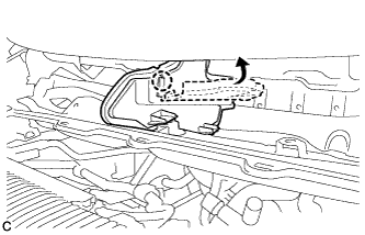
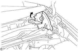
Connect the suction pipe sub-assembly.
-
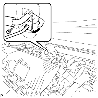
Rotate the hook connector in the direction indicated by the arrow in the illustration.
-
Insert the pipe joint into the fitting hole securely and tighten the bolt.
- Torque:
- 9.8 N*m { 100 kgf*cm, 87 in.*lbf }
-
-
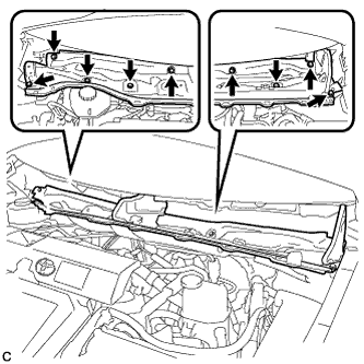
INSTALL OUTER COWL TOP PANEL SUB-ASSEMBLY (for LHD)
-
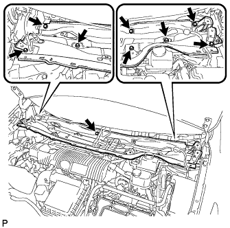
Install the outer cowl top panel sub-assembly with the 9 bolts.
- Torque:
- 12 N*m { 122 kgf*cm, 9 ft.*lbf }
-
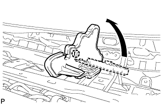
Bend the water guard plate RH and engage the claw.
-
Bend the No. 1 heater air duct splash shield seal and engage the claw.
-
Engage the clamp to install the wire harness.
-
-
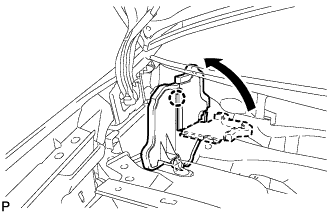
INSTALL COWL BODY MOUNTING REINFORCEMENT LH (for LHD)
-
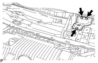
Install the cowl body mounting reinforcement LH with the 3 bolts.
- Torque:
- 12 N*m { 122 kgf*cm, 9 ft.*lbf }
-
-
INSTALL OUTER COWL TOP PANEL SUB-ASSEMBLY (for RHD)
-
Install the outer cowl top panel sub-assembly with the 9 bolts.
- Torque:
- 12 N*m { 122 kgf*cm, 9 ft.*lbf }
-
Bend the water guard plate RH and engage the claw.
-
Bend the No. 1 heater air duct splash shield seal and engage the claw.
-
Engage the clamp*2 of the wire harness.
-
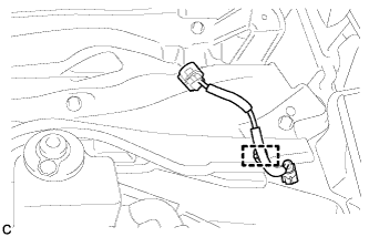
Engage the clamp*1 and connect the connector (w/ Windshield Deicer).
-
Engage the clamp of the wire harness.
-
-
INSTALL COWL BODY MOUNTING REINFORCEMENT RH (for RHD)
-
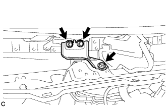
Install the cowl body mounting reinforcement RH with the 3 bolts.
- Torque:
- 12 N*m { 122 kgf*cm, 9 ft.*lbf }
-
-
INSTALL WINDSHIELD WIPER MOTOR AND LINK ASSEMBLY
-
CHARGE AIR CONDITIONING SYSTEM WITH REFRIGERANT
-
Perform vacuum purging using a vacuum pump or appropriate equipment.
-
Charge the air conditioning system with refrigerant.
Refrigerant type HFC-134a (R134a) 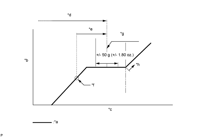
Text in Illustration *a Sub-cool System *b High Pressure *c Refrigerant Amount *d Standard charge amount *e Charge additional 100 g (3.5 oz.) *f Point where bubbles disappear *g Mean value in proper range *h Overcharged Standard charge amount 440 to 500g (15.5 to 17.6oz.) - SST
- 09985-20010 ( 09985-02010, 09985-02050, 09985-02060, 09985-02070, 09985-02080, 09985-02090, 09985-02110, 09985-02130, 09985-02140, 09985-02150 )
Note
-
Do not turn the A/C switch on before charging the air conditioning system with refrigerant. Doing so may cause the compressor to work without refrigerant, resulting in overheating of the compressor.
-
The refrigerant amount should be checked by quantity (weight).
Tech Tips
Ensure that sufficient refrigerant is available to recharge the system when using a refrigerant recovery unit. Refrigerant recovery units are not always able to recover 100% of the refrigerant from an air conditioning system.
-
-
WARM UP COMPRESSOR
-
Keep the A/C switch on for at least 2 minutes to warm up the compressor.
Note
To prevent damage to the compressor, be sure to warm up the compressor when turning the air conditioning on after removing and installing air conditioning system lines (including the compressor).
-
-
INSPECT FOR REFRIGERANT LEAK
-
After recharging the air conditioning system with refrigerant, inspect for refrigerant leaks using a halogen leak detector.
-
Carry out the test under the following conditions:
-
Power switch off.
-
Secure good ventilation (the halogen leak detector may react to volatile gases which are not refrigerant, such as gasoline vapor and exhaust gas).
-
Repeat the inspection 2 or 3 times.
-
Measure the pressure to make sure that there is some refrigerant remaining in the air conditioning system.
Pressure when the compressor is off: approx. 392 to 588 kPa (3.9 to 5.9 kgf/cm2, 57 to 85 psi)
-
-
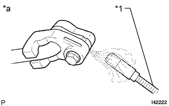
Text in Illustration *1 Halogen Leak Detector *a Inspect for Leak Using a halogen leak detector, inspect for refrigerant leaks from the air conditioning system.
-
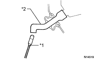
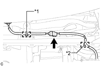
Text in Illustration *1 Halogen Leak Detector *2 Drain Hose Bring the halogen leak detector close to the drain hose with the detector power off, and then turn the detector on.
Tech Tips
-
After the blower motor has stopped, leave the cooling unit for more than 15 minutes.
-
Bring the halogen leak detector sensor under the drain hose.
-
When bringing the halogen leak detector close to the drain hose, make sure that the halogen leak detector does not react to volatile gases. If it is not possible to avoid interference from volatile gases, the vehicle should be lifted up to allow checking for leaks.
-
-
If a refrigerant leak is not detected from the drain hose, remove the blower motor control from the cooling unit. Insert the halogen leak detector sensor into the unit and check for a leak.
-
Disconnect the pressure sensor connector and leave it for approximately 20 minutes. Bring the halogen leak detector close to the pressure sensor and check for a leak.
Tech Tips
When checking for leaks, the presence of oily dirt at a joint can indicate a leak.
-