SEAT BELT WARNING SYSTEM Rear Seat Belt Warning Light Malfunction
DESCRIPTION
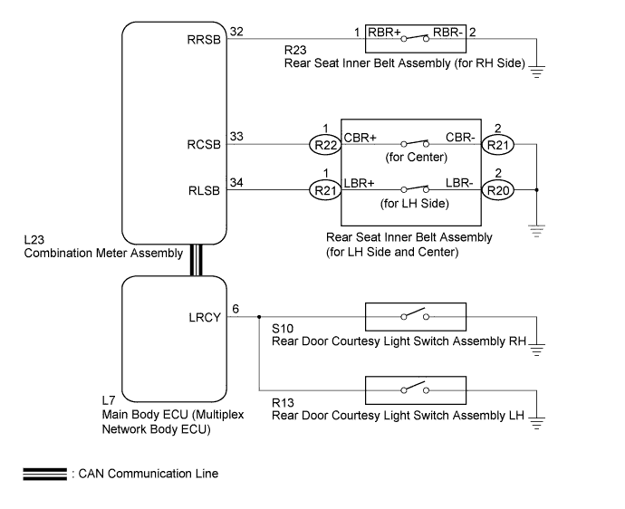
When a rear seat belt is not fastened after a rear door is opened and closed with the power switch on (IG), the rear seat belt warning is shown on the multi-information display in the combination meter assembly. The main body ECU (multiplex network body ECU) detects whether any of the rear doors are open or closed based on the courtesy switch condition and then sends the rear door status signal to the combination meter assembly. The rear seat inner belt assembly detects whether the seat belt is fastened or not fastened based on each buckle switch condition and then sends the seat belt status signal to the combination meter assembly. When the combination meter assembly detects that any courtesy switch is turned off while the power switch is on (IG), or that any courtesy switch is turned off and then the power switch is turned on (IG), the combination meter assembly shows the rear seat belt warning on the multi-information display. Then the combination meter assembly shows the current status of the rear seat belts according to each buckle switch condition.
WIRING DIAGRAM
INSPECTION PROCEDURE
PROCEDURE
-
CHECK REAR SEAT BELT WARNING
-
Turn the power switch off and lock all doors.
-
Unlock all doors and turn the power switch on (IG).
-
Open and close the rear RH door. Then, check that the multi-information display on the combination meter assembly displays the rear seat belt warning.
OK The rear seat belt warning is displayed. -
Turn the power switch off and lock all doors.
-
Unlock all doors and turn the power switch on (IG).
-
Open and close the rear LH door. Then, check that the multi-information display on the combination meter assembly displays the rear seat belt warning.
OK The rear seat belt warning is displayed. -
Turn the power switch off and lock all doors.
-
Unlock all doors and turn the power switch on (IG). Then, check that the multi-information display on the combination meter assembly does not display the rear seat belt warning.
OK The rear seat belt warning is not displayed.
NG 
READ VALUE USING GTS (REAR DOOR COURTESY SWITCH) Click here
OK 
-
-
READ VALUE USING GTS (REAR SEAT BELT BUCKLE SWITCH)
-
Connect the GTS to the DLC3.
-
Turn the power switch on (IG).
-
Turn the GTS on.
-
Enter the following menus: Body Electrical / Combination Meter / Data List.
-
Read the Data List according to the display on the GTS.
Combination Meter Tester Display Measurement Item/Range Normal Condition Diagnostic Note 2nd-Row Seatbelt Buckle (R) Rear RH side seat belt buckle switch signal/ON or OFF ON: Rear RH side seat belt fastened
OFF: Rear RH side seat belt not fastened
- 2nd-Row Seatbelt Buckle (L) Rear LH side seat belt buckle switch signal/ON or OFF ON: Rear LH side seat belt fastened
OFF: Rear LH side seat belt not fastened
- 2nd-Row Seatbelt Buckle (C) Rear center seat belt buckle switch signal/ON or OFF ON: Rear center seat belt fastened
OFF: Rear center seat belt not fastened
- OK ON or OFF appears on the tester screen according to the rear seat belt condition. Result Result Proceed to OK or NG (for all buckle switches) A NG (for rear RH side buckle switch) B NG (for rear center buckle switch) C NG (for rear LH side buckle switch) D NG (for rear center and LH side buckle switches) E
B
INSPECT REAR SEAT INNER BELT ASSEMBLY (FOR RH SIDE) Click here
C
INSPECT REAR SEAT INNER BELT ASSEMBLY (FOR CENTER) Click here
D
INSPECT REAR SEAT INNER BELT ASSEMBLY (FOR LH SIDE) Click here
E
CHECK HARNESS AND CONNECTOR (REAR SEAT INNER BELT (FOR LH SIDE AND CENTER) - BODY GROUND) Click here
A 
REPLACE NO. 3 METER CIRCUIT PLATE Click here
-
-
READ VALUE USING GTS (REAR DOOR COURTESY SWITCH)
-
Connect the GTS to the DLC3.
-
Turn the power switch on (IG).
-
Turn the GTS on.
-
Enter the following menus: Body Electrical / Main Body / Data List.
-
Read the Data List according to the display on the GTS.
Main Body Tester Display Measurement Item/Range Normal Condition Diagnostic Note RR Door Courtesy SW Rear door courtesy switch signal/ON or OFF ON: Rear door LH or RH open
OFF: Rear door LH and RH closed
- RL Door Courtesy SW Rear door courtesy switch signal/ON or OFF ON: Rear door LH or RH open
OFF: Rear door LH and RH closed
- OK ON or OFF appears on the tester screen according to the rear door condition.
NG 
GO TO LIGHTING SYSTEM Click here
OK
-
-
REPLACE NO. 3 METER CIRCUIT PLATE
-
Replace the No. 3 meter circuit plate Click here.
NEXT
-
-
CHECK REAR SEAT BELT WARNING
-
Check the rear seat belt warning function Click here.
OK The rear seat belt warning function operates normally.
NG
REPLACE MAIN BODY ECU (MULTIPLEX NETWORK BODY ECU) Click here
OK
END (NO. 3 METER CIRCUIT PLATE WAS DEFECTIVE)
-
-
INSPECT REAR SEAT INNER BELT ASSEMBLY (FOR RH SIDE)
-
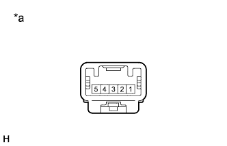
Text in Illustration *a Component without harness connected
(Rear Seat Inner Belt Assembly (for RH Side))
Remove the rear seat inner belt assembly (for RH side) Click here.
-
Measure the resistance according to the value(s) in the table below.
Standard Resistance Tester Connection Condition Specified Condition 1 - 2 Rear seat belt RH not fastened Below 1 Ω 1 - 2 Rear seat belt RH fastened 10 kΩ or higher
NG
REPLACE REAR SEAT INNER BELT ASSEMBLY (FOR RH SIDE) Click here
OK
-
-
CHECK HARNESS AND CONNECTOR (REAR SEAT INNER BELT ASSEMBLY (FOR RH SIDE) - COMBINATION METER ASSEMBLY)
-
Disconnect the L23 combination meter assembly connector.
-
Measure the resistance according to the value(s) in the table below.
Standard Resistance Tester Connection Condition Specified Condition L23-32 (RRSB) - R23-1 (RBR+) Always Below 1 Ω L23-32 (RRSB) - Body ground Always 10 kΩ or higher R23-2 (RBR-) - Body ground Always Below 1 Ω
NG
REPAIR OR REPLACE HARNESS OR CONNECTOR
OK
REPLACE NO. 3 METER CIRCUIT PLATE Click here
-
-
INSPECT REAR SEAT INNER BELT ASSEMBLY (FOR CENTER)
-
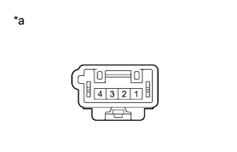
Text in Illustration *a Component without harness connected
(Rear Seat Inner Belt Assembly (for LH Side and Center))
Remove the rear seat inner belt assembly (for LH side and center) Click here.
-
Measure the resistance according to the value(s) in the table below.
Standard Resistance Tester Connection Condition Specified Condition 1 - 2 Rear seat belt center not fastened Below 1 Ω 1 - 2 Rear seat belt center fastened 10 kΩ or higher
NG
REPLACE REAR SEAT INNER BELT ASSEMBLY (FOR LH SIDE AND CENTER) Click here
OK
-
-
CHECK HARNESS AND CONNECTOR (REAR SEAT INNER BELT ASSEMBLY (FOR CENTER) - COMBINATION METER ASSEMBLY)
-
Disconnect the L23 combination meter assembly connector.
-
Measure the resistance according to the value(s) in the table below.
Standard Resistance Tester Connection Condition Specified Condition L23-33 (RCSB) - R22-1 (CBR+) Always Below 1 Ω L23-33 (RCSB) - Body ground Always 10 kΩ or higher R22-2 (CBR-) - Body ground Always Below 1 Ω
NG
REPAIR OR REPLACE HARNESS OR CONNECTOR
OK
REPLACE NO. 3 METER CIRCUIT PLATE Click here
-
-
INSPECT REAR SEAT INNER BELT ASSEMBLY (FOR LH SIDE)
-
Text in Illustration *a Component without harness connected
(Rear Seat Inner Belt Assembly (for LH Side and Center))
Remove the rear seat inner belt assembly (for LH side and center) Click here.
-
Measure the resistance according to the value(s) in the table below.
Standard Resistance Tester Connection Condition Specified Condition 1 - 2 Rear seat belt LH not fastened Below 1 Ω 1 - 2 Rear seat belt LH fastened 10 kΩ or higher
NG
REPLACE REAR SEAT INNER BELT ASSEMBLY (FOR LH SIDE AND CENTER) Click here
OK
-
-
CHECK HARNESS AND CONNECTOR (REAR SEAT INNER BELT ASSEMBLY (FOR LH SIDE) - COMBINATION METER ASSEMBLY)
-
Disconnect the L23 combination meter assembly connector.
-
Measure the resistance according to the value(s) in the table below.
Standard Resistance Tester Connection Condition Specified Condition L23-34 (RLSB) - R21-1 (LBR+) Always Below 1 Ω L23-34 (RLSB) - Body ground Always 10 kΩ or higher R21-2 (LBR-) - Body ground Always Below 1 Ω
NG
REPAIR OR REPLACE HARNESS OR CONNECTOR
OK
REPLACE NO. 3 METER CIRCUIT PLATE Click here
-
-
CHECK HARNESS AND CONNECTOR (REAR SEAT INNER BELT (FOR LH SIDE AND CENTER) - BODY GROUND)
-
Disconnect the R22 and R21 rear seat inner belt assembly (for LH side and center) connectors.
-
Measure the resistance according to the value(s) in the table below.
Standard Resistance Tester Connection Condition Specified Condition R22-2 (CBR-) - Body ground Always Below 1 Ω R21-2 (LBR-) - Body ground Always Below 1 Ω
NG
REPAIR OR REPLACE HARNESS OR CONNECTOR
OK
REPLACE NO. 3 METER CIRCUIT PLATE Click here
-