SEAT BELT WARNING SYSTEM Front Passenger Side Seat Belt Warning Light Malfunction
DESCRIPTION
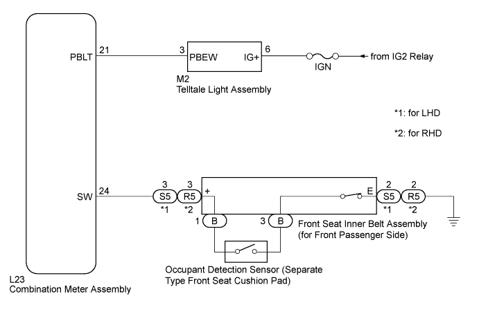
When the front passenger side seat belt is not fastened with the power switch on (IG) and the front passenger side seat occupied, the front passenger side seat belt warning light blinks. The occupant detection sensor (separate type front seat cushion pad) detects if the front passenger side seat is occupied and sends signals to the combination meter assembly. The front seat inner belt assembly detects the front passenger side seat belt condition and sends signals to the combination meter assembly. After receiving the signals from the occupant detection sensor (separate type front seat cushion pad) and front seat inner belt assembly, the combination meter illuminates the front passenger side seat belt warning light.
WIRING DIAGRAM
INSPECTION PROCEDURE
Note
Inspect the fuses for circuits related to this system before performing the following inspection procedure.
PROCEDURE
-
READ VALUE USING GTS
-
Connect the GTS to the DLC3.
-
Turn the power switch on (IG).
-
Turn the GTS on.
-
Enter the following menus: Body Electrical / Combination Meter / Data List.
-
Read the Data List according to the display on the GTS.
Combination Meter Tester Display Measurement Item/Range Normal Condition Diagnostic Note P-Seatbelt Buckle SW Front passenger side seat belt buckle switch signal/ON or OFF ON: Front passenger side seat belt fastened
OFF: Front passenger side seat belt not fastened
- OK ON or OFF appears on the tester screen according to the front passenger side seat belt condition.
NG 
CHECK HARNESS AND CONNECTOR (FRONT SEAT INNER BELT ASSEMBLY (FOR FRONT PASSENGER SIDE) - COMBINATION METER ASSEMBLY) Click here
OK 
-
-
PERFORM ACTIVE TEST USING GTS
-
Connect the GTS to the DLC3.
-
Turn the power switch on (IG).
-
Turn the GTS on.
-
Enter the following menus: Body Electrical / Combination Meter / Active Test.
-
Perform the Active Test according to the display on the GTS.
Combination Meter Tester Display Test Part Control Range Diagnostic Note Front Passenger Side Seat Belt Front passenger side seat belt warning light OFF or ON - OK The front passenger side seat belt warning light operates normally.
NG
CHECK HARNESS AND CONNECTOR (TELLTALE LIGHT ASSEMBLY - AUXILIARY BATTERY) Click here
OK 
REPLACE NO. 3 METER CIRCUIT PLATE Click here
-
-
CHECK HARNESS AND CONNECTOR (FRONT SEAT INNER BELT ASSEMBLY (FOR FRONT PASSENGER SIDE) - COMBINATION METER ASSEMBLY)
-
Disconnect the L23 combination meter assembly connector.
-
Disconnect the S5*1 or R5*2 front seat inner belt assembly (for front passenger side) connector.
-
*1: for LHD
-
*2: for RHD
-
-
Measure the resistance according to the value(s) in the table below.
Standard Resistance Tester Connection Condition Specified Condition L23-24 (SW) - S5-3 (+)*1
L23-24 (SW) - R5-3 (+)*2
Always Below 1 Ω L23-24 (SW) - Body ground Always 10 kΩ or higher S5-2 (E) - Body ground*1
R5-2 (E) - Body ground*2
Always Below 1 Ω
-
*1: for LHD
-
*2: for RHD
-
NG 
REPAIR OR REPLACE HARNESS OR CONNECTOR
OK
-
-
INSPECT OCCUPANT DETECTION SENSOR (SEPARATE TYPE FRONT SEAT CUSHION PAD)
-
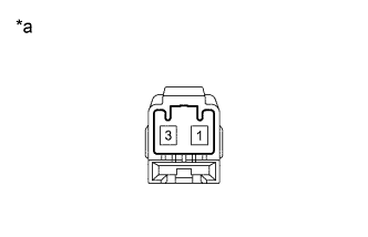
Text in Illustration *a Component without harness connected
(Occupant Detection Sensor (Separate Type Front Seat Cushion Pad))
Remove the occupant detection sensor (separate type front seat cushion pad) Click here.
-
Measure the resistance according to the value(s) in the table below.
Standard Resistance Tester Connection Condition Specified Condition 1 - 3 Front passenger side seat occupied Below 100 Ω 1 - 3 Front passenger side seat not occupied 1 MΩ or higher
NG
REPLACE OCCUPANT DETECTION SENSOR (SEPARATE TYPE FRONT SEAT CUSHION PAD) Click here
OK
-
-
INSPECT FRONT SEAT INNER BELT ASSEMBLY (FOR FRONT PASSENGER SIDE)
-
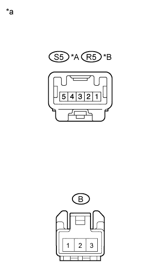
Text in Illustration *A for LHD *B for RHD *a Component without harness connected
(Front Seat Inner Belt Assembly (for Front Passenger Side))
Remove the front seat inner belt assembly (for front passenger side) Click here.
-
Measure the resistance according to the value(s) in the table below.
Standard Resistance Tester Connection Condition Specified Condition S5-3 (+) - B-1*1
R5-3 (+) - B-1*2
Always Below 1 Ω S5-2 (E) - B-3*1
R5-2 (E) - B-3*2
Front passenger side seat belt not fastened Below 1 Ω S5-2 (E) - B-3*1
R5-2 (E) - B-3*2
Front passenger side seat belt fastened 10 kΩ or higher
-
*1: for LHD
-
*2: for RHD
-
NG
REPLACE FRONT SEAT INNER BELT ASSEMBLY (FOR FRONT PASSENGER SIDE) Click here
OK
REPLACE NO. 3 METER CIRCUIT PLATE Click here
-
-
CHECK HARNESS AND CONNECTOR (TELLTALE LIGHT ASSEMBLY - AUXILIARY BATTERY)
-
Disconnect the M2 telltale light assembly connector.
-
Measure the voltage according to the value(s) in the table below.
Standard Voltage Tester Connection Condition Specified Condition M2-6 (IG+) - Body ground Power switch on (IG) 11 to 14 V M2-6 (IG+) - Body ground Power switch off Below 1 V
NG
REPAIR OR REPLACE HARNESS OR CONNECTOR
OK
-
-
CHECK HARNESS AND CONNECTOR (COMBINATION METER ASSEMBLY - TELLTALE LIGHT ASSEMBLY)
-
Disconnect the L23 combination meter assembly connector.
-
Measure the resistance according to the value(s) in the table below.
Standard Resistance Tester Connection Condition Specified Condition L23-21 (PBLT) - M2-3 (PBEW) Always Below 1 Ω L23-21 (PBLT)- Body ground Always 10 kΩ or higher
NG
REPAIR OR REPLACE HARNESS OR CONNECTOR
OK
-
-
CHECK HARNESS AND CONNECTOR (COMBINATION METER ASSEMBLY - AUXILIARY BATTERY)
-
Reconnect the M2 telltale light assembly connector.
-
Measure the voltage according to the value(s) in the table below.
Standard Voltage Tester Connection Condition Specified Condition L23-21 (PBLT) - Body ground Power switch on (IG) 11 to 14 V L23-21 (PBLT) - Body ground Power switch off Below 1 V
NG
REPLACE TELLTALE LIGHT ASSEMBLY Click here
OK
REPLACE NO. 3 METER CIRCUIT PLATE Click here
-