METER / GAUGE SYSTEM Headup Display Malfunction
DESCRIPTION
The headup display system displays some vehicle information on the windshield glass. The headup display system consists of the combination mirror meter ECU and combination meter assembly.
The combination mirror meter ECU receives information from the combination meter assembly via communication and projects it on the windshield.
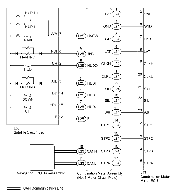
WIRING DIAGRAM
INSPECTION PROCEDURE
Tech Tips
Before starting the following inspection, confirm the headup display (combination meter mirror ECU) position and illuminance, then perform the on-vehicle inspection Click here.
PROCEDURE
-
SYSTEM CHECK
-
Check the symptom of the headup display (combination meter mirror ECU).
Result Result Proceed to Headup display (combination meter mirror ECU) does not operate at all. A Cruise information display does not change. B
B 
READ VALUE USING GTS (HEAD UP DISPLAY SWITCH) Click here
A 
-
-
CHECK HARNESS AND CONNECTOR (HEADUP DISPLAY CIRCUIT)
-
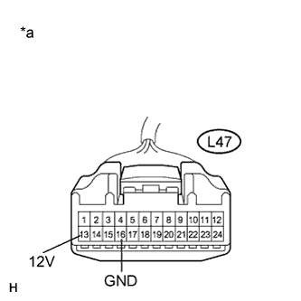
Text in Illustration *a Front view of wire harness connector
(to Headup Display (Combination Meter Mirror ECU))
Disconnect the L47 combination meter mirror ECU connector.
-
Measure the voltage according to the value(s) in the table below.
Standard Voltage Tester Connection Condition Specified Condition L47-13 (12V) - Body ground Power switch on (IG) 11 to 14 V -
Measure the resistance according to the value(s) in the table below
Standard Resistance Tester Connection Condition Specified Condition L47-16 (GND) - Body ground Always Below 1 Ω
NG 
REPAIR OR REPLACE HARNESS OR CONNECTOR
OK 
REPLACE HEADUP DISPLAY (COMBINATION METER MIRROR ECU) Click here
-
-
READ VALUE USING GTS (HEAD UP DISPLAY SWITCH)
-
Connect the GTS to the DLC3.
-
Turn the power switch on (IG).
-
Turn the GTS on.
-
Enter the following menus: Body Electrical / Combination Meter / Data List.
-
Check the values by referring to the table below.
Combination Meter Tester Display Measurement Item/Range Normal Condition Diagnostic Note Head Up Display Switch (Up) Headup display position up switch/OFF or ON OFF: Headup display position up switch not pressed - ON: Headup display position up switch pressed - Head Up Display Switch (Down) Headup display position down switch/OFF or ON OFF: Headup display position down switch not pressed - ON: Headup display position down switch pressed - Head Up Display Switch (Main) Headup display main switch/OFF or ON OFF: Headup display main switch not pressed - ON: Headup display main switch pressed - OK Each switch condition displayed on the GTS changes with the actual switch operation.
B
CHECK HARNESS AND CONNECTOR (HEADUP DISPLAY - COMBINATION METER ASSEMBLY) Click here
A
REPLACE NO. 3 METER CIRCUIT PLATE Click here
-
-
CHECK HARNESS AND CONNECTOR (HEADUP DISPLAY - COMBINATION METER ASSEMBLY)
-
Disconnect the L47 combination meter mirror ECU and L24 combination meter assembly connectors.
-
Measure the resistance according to the value(s) in the table below.
Standard Resistance Tester Connection Condition Specified Condition L47-17 (BKR) - L24-5 (BKR) Always Below 1 Ω L47-17 (BKR) - Body ground Always 10 kΩ or higher L47-18 (LAT) - L24-6 (LAT) Always Below 1 Ω L47-18 (LAT) - Body ground Always 10 kΩ or higher L47-19 (CLKH) - L24-7 (CLKH) Always Below 1 Ω L47-19 (CLKH) - Body ground Always 10 kΩ or higher L47-20 (CLKL) - L24-8 (CLKL) Always Below 1 Ω L47-20 (CLKL) - Body ground Always 10 kΩ or higher L47-21 (SIH) - L24-9 (SIH) Always Below 1 Ω L47-21 (SIH) - Body ground Always 10 kΩ or higher L47-22 (SIL) - L24-10 (SIL) Always Below 1 Ω L47-22 (SIL) - Body ground Always 10 kΩ or higher L47-23 (WE) - L24-11 (WE) Always Below 1 Ω L47-23 (WE) - Body ground Always 10 kΩ or higher L47-2 (STP1) - L24-14 (STP1) Always Below 1 Ω L47-2 (STP1) - Body ground Always 10 kΩ or higher L47-3 (STP2) - L24-15 (STP2) Always Below 1 Ω L47-3 (STP2) - Body ground Always 10 kΩ or higher L47-4 (STP3) - L24-16 (STP3) Always Below 1 Ω L47-4 (STP3) - Body ground Always 10 kΩ or higher L47-5 (STP4) - L24-17 (STP4) Always Below 1 Ω L47-5 (STP4) - Body ground Always 10 kΩ or higher
NG
REPAIR OR REPLACE HARNESS OR CONNECTOR
OK
-
-
INSPECT SATELLITE SWITCH SET
-
Remove the satellite switch set Click here.
-
Measure the resistance according to the value(s) in the table below.
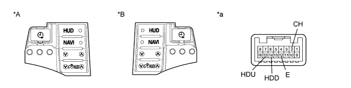
Standard Resistance Tester Connection Switch Condition Specified Condition 2 (CH) - 12 (E) HUD switch pressed Below 1 Ω Always 10 kΩ or higher 14 (HDD) - 12 (E) Down switch pressed Below 1 Ω Always 10 kΩ or higher 15 (HDU) - 12 (E) Up switch pressed Below 1 Ω Always 10 kΩ or higher Text in Illustration *A for LHD *B for RHD *a Component without harness connected
(Satellite Switch Set)
- -
NG
REPLACE SATELLITE SWITCH SET Click here
OK
-
-
CHECK HARNESS AND CONNECTOR (SATELLITE SWITCH SET - COMBINATION METER ASSEMBLY)
-
Disconnect the L50 satellite switch set and L25 combination meter assembly connectors.
-
Measure the resistance according to the value(s) in the table below.
Standard Resistance Tester Connection Condition Specified Condition L50-12 (E) - L25-2 (E) Always Below 1 Ω L50-12 (E) - Body ground Always 10 kΩ or higher L50-15 (HDU) - L25-7 (HUDU) Always Below 1 Ω L50-15 (HDU) - Body ground Always 10 kΩ or higher L50-14 (HDD) - L25-4 (HUDD) Always Below 1 Ω L50-14 (HDD) - Body ground Always 10 kΩ or higher L50-3 (TAIL) - L25-3 (HUDI) Always Below 1 Ω L50-3 (TAIL) - Body ground Always 10 kΩ or higher L50-2 (CH) - L25-8 (HUDO) Always Below 1 Ω L50-2 (CH) - Body ground Always 10 kΩ or higher L50-6 (NVI) - L25-9 (IIND) Always Below 1 Ω L50-6 (NVI) - Body ground Always 10 kΩ or higher L50-7 (NVM) - L25-1 (NVSW) Always Below 1 Ω L50-7 (NVM) - Body ground Always 10 kΩ or higher
NG
REPAIR OR REPLACE HARNESS OR CONNECTOR
OK
-
-
REPLACE HEADUP DISPLAY (COMBINATION METER MIRROR ECU)
-
Replace the headup display (combination meter mirror ECU) with a new or known good one Click here.
OK The operation of the headup display (combination meter mirror ECU) returns to normal.
NG
REPLACE NO. 3 METER CIRCUIT PLATE Click here
OK
END
-