METER / GAUGE SYSTEM Operating Light Control Rheostat does not Change Light Brightness
DESCRIPTION
The combination meter assembly receives signals from this circuit to adjust the illumination of the meter. The combination meter assembly sets the illumination level based on the user operation of the light control rheostat.
Tech Tips
-
The meter illumination level can be adjusted by operating the light control rheostat.
-
The meter illumination dims when the light control switch is turned to the tail, head, or AUTO position at night.
-
Setting the meter illumination to maximum brightness cancels the above dimming of the meter illumination.
-
Setting the meter illumination to minimum brightness almost turns off (very dim) the meter illumination when the light control switch is changed to the tail, head, or AUTO position at night.
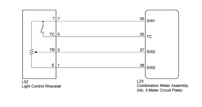
WIRING DIAGRAM
INSPECTION PROCEDURE
PROCEDURE
-
SYSTEM CHECK
-
Confirm the symptoms.
Result Result Proceed to Meter illumination does not change when operating the light control rheostat. A Dimmer function cannot be canceled. B
B 
READ VALUE USING GTS (TAIL CANCEL SW) Click here
A 
-
-
READ VALUE USING GTS (RHEOSTAT VALUE)
-
Connect the GTS to the DLC3.
-
Turn the power switch on (IG).
-
Turn the GTS on.
-
Enter the following menus: Body Electrical / Combination Meter / Data List.
-
Check the values by referring to the table below.
Combination Meter Tester Display Measurement Item/Range Normal Condition Diagnostic Note Rheostat value Light control rheostat/Min.: 0, Max.: 100 (%) Light control rheostat value 0 (dark) The value changes with rheostat operation Light control rheostat value 100 (bright) OK The value displayed on the GTS gradually changes with actual rheostat knob operation.
NG
INSPECT LIGHT CONTROL RHEOSTAT Click here
OK 
REPLACE NO. 3 METER CIRCUIT PLATE Click here
-
-
INSPECT LIGHT CONTROL RHEOSTAT
-
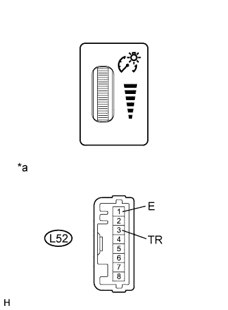
Text in Illustration *a Component without harness connected
(Light Control Rheostat)
Remove the light control rheostat Click here.
-
Measure the resistance according to the value(s) in the table below.
Standard Resistance Tester Connection Switch Condition Specified Condition L52-3 (TR) - L52-1 (E) Light control rheostat knob fully downwards (MIN.) Below 50 Ω Light control rheostat knob between MIN. and MAX. The value changes gradually (Between 0 to 12 kΩ) Light control rheostat knob fully upwards (MAX.) 8 to 12 kΩ
NG 
REPLACE LIGHT CONTROL RHEOSTAT Click here
OK
-
-
CHECK HARNESS AND CONNECTOR (COMBINATION METER ASSEMBLY - LIGHT CONTROL RHEOSTAT)
-
Disconnect the L23 combination meter assembly connector.
-
Measure the resistance according to the value(s) in the table below.
Standard Resistance Tester Connection Condition Specified Condition L23-37 (SW2) - L52-3 (TR) Always Below 1 Ω L23-37 (SW2) - Body ground Always 10 kΩ or higher L23-38 (SW3) - L52-1 (E) Always Below 1 Ω L23-38 (SW3) - Body ground Always 10 kΩ or higher
NG
REPAIR OR REPLACE HARNESS OR CONNECTOR
OK
REPLACE NO. 3 METER CIRCUIT PLATE Click here
-
-
READ VALUE USING GTS (TAIL CANCEL SW)
-
Connect the GTS to the DLC3.
-
Turn the power switch on (IG).
-
Turn the GTS on.
-
Enter the following menus: Body Electrical / Combination Meter / Data List.
-
Check the values by referring to the table below.
Combination Meter Tester Display Measurement Item/Range Normal Condition Diagnostic Note Tail Cancel SW Tail cancel switch/OFF or ON OFF: Tail cancel switch off Dimming of dash lights is possible ON: Tail cancel switch on Dimming of dash lights is canceled Tech Tips
The tail cancel switch is operated by turning the light control rheostat knob fully upward.
OK Condition displayed on the GTS is the same as the actual light control rheostat knob position.
NG
INSPECT LIGHT CONTROL RHEOSTAT Click here
OK
REPLACE NO. 3 METER CIRCUIT PLATE Click here
-
-
INSPECT LIGHT CONTROL RHEOSTAT
-
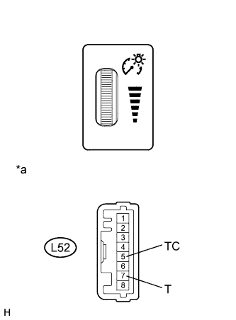
Text in Illustration *a Component without harness connected
(Light Control Rheostat)
Remove the light control rheostat Click here.
-
Measure the resistance according to the value(s) in the table below.
Standard Resistance Tester Connection Switch Condition Specified Condition L52-5 (TC) - L52-7 (T) Light control rheostat knob not fully upward 10 kΩ or higher Light control rheostat knob fully upwards (Tail cancel switch is on) Below 1 Ω
NG
REPLACE LIGHT CONTROL RHEOSTAT Click here
OK
-
-
CHECK HARNESS AND CONNECTOR (COMBINATION METER ASSEMBLY - LIGHT CONTROL RHEOSTAT)
-
Disconnect the L23 combination meter assembly connector.
-
Measure the resistance according to the value(s) in the table below.
Standard Resistance Tester Connection Condition Specified Condition L23-36 (SW1) - L52-7 (T) Always Below 1 Ω L23-36 (SW1) - Body ground Always 10 kΩ or higher L23-35 (TC) - L52-5 (TC) Always Below 1 Ω L23-35 (TC) - Body ground Always 10 kΩ or higher
NG
REPAIR OR REPLACE HARNESS OR CONNECTOR
OK
REPLACE NO. 3 METER CIRCUIT PLATE Click here
-