METER / GAUGE SYSTEM, Diagnostic DTC:B1504
| DTC Code | DTC Name |
|---|---|
| B1504 | Lost Communication with Steering SW |
DESCRIPTION
The combination meter assembly communicates with the steering pad switch via a direct line. If the combination meter assembly detects a communication malfunction, it stores this DTC.
| DTC No. | DTC Detection Condition | Trouble Area |
|---|---|---|
| B1504 | When the IG voltage is 9.5 V or more and power switch on (IG) and the following condition is detected:
|
|
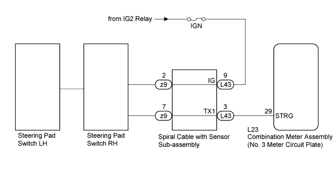
WIRING DIAGRAM
INSPECTION PROCEDURE
Note
Inspect the fuses of circuits related to this system before performing the following inspection procedure.
PROCEDURE
-
READ VALUE USING GTS (MULTI DISPLAY SELECT SWITCH, DRIVE MONITOR RESET SW)
-
Connect the GTS to the DLC3.
-
Turn the power switch on (IG).
-
Turn the GTS on.
-
Enter the following menus: Body Electrical / Combination Meter / Data List.
-
Check the values by referring to the table below.
Combination Meter Tester Display Measurement Item/Range Normal Condition Diagnostic Note Multi Display Select Switch DISP switch in the steering pad switch RH/OFF or ON OFF: DISP switch in the steering pad switch RH not pressed - ON: DISP switch in the steering pad switch RH pressed - Drive Monitor Reset SW TRIP switch in the steering pad switch RH/OFF or ON OFF: TRIP switch in the steering pad switch RH not pressed - ON: TRIP switch in the steering pad switch RH pressed more than 1 second - OK Steering pad switch RH condition displayed on the GTS changes with the actual switch operation.
NG 
INSPECT SPIRAL CABLE WITH SENSOR SUB-ASSEMBLY Click here
OK 
REPLACE NO. 3 METER CIRCUIT PLATE Click here
-
-
INSPECT SPIRAL CABLE WITH SENSOR SUB-ASSEMBLY
-
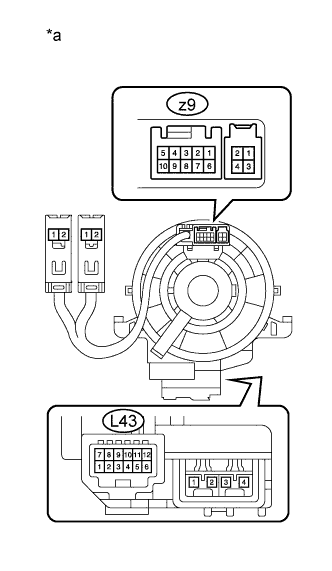
Text in Illustration *a Component without harness connected
(Spiral Cable with Sensor Sub-assembly)
Disconnect the L43 and z9 spiral cable with sensor sub-assembly connectors.
-
Measure the resistance according to the value(s) in the table below.
Standard Resistance Tester Connection Condition Specified Condition L43-3 (TX1) - z9-7 Always Below 1 Ω L43-9 (IG) - z9-2 Always Below 1 Ω
NG 
REPLACE SPIRAL CABLE WITH SENSOR SUB-ASSEMBLY Click here
OK 
-
-
CHECK HARNESS AND CONNECTOR (SPIRAL CABLE WITH SENSOR SUB-ASSEMBLY - IG2 RELAY)
-
Measure the voltage according to the value(s) in the table below.
Standard Voltage Tester Connection Condition Specified Condition L43-9 (IG) - Body ground Power switch off Below 1 V L43-9 (IG) - Body ground Power switch on (IG) 11 to 14 V
NG
REPAIR OR REPLACE HARNESS OR CONNECTOR
OK
-
-
CHECK HARNESS AND CONNECTOR (COMBINATION METER ASSEMBLY - STEERING PAD SWITCH RH)
-
Measure the resistance according to the value(s) in the table below.
Standard Resistance Tester Connection Condition Specified Condition L23-29 (STRG) - L43-3 (TX1) Always Below 1 Ω L23-29 (STRG) - Body ground Always 10 kΩ or higher
NG
REPAIR OR REPLACE HARNESS OR CONNECTOR
OK
-
-
REPLACE STEERING PAD SWITCH RH
-
Replace the steering pad switch RH with a new or known good one Click here.
OK The operation of the combination meter assembly returns to normal.
NG
REPLACE STEERING PAD SWITCH LH Click here
OK
END
-
-
REPLACE STEERING PAD SWITCH LH
-
Replace the steering pad switch LH with a new or known good one Click here.
OK The operation of the combination meter assembly returns to normal.
NG
REPLACE NO. 3 METER CIRCUIT PLATE Click here
OK
END
-