ENGINE IMMOBILISER SYSTEM, Diagnostic DTC:B279A
| DTC Code | DTC Name |
|---|---|
| B279A | Theft Deterrent System Communication Line High Fixation |
DESCRIPTION
If the communication line (EFIO - IMI) to the certification ECU assembly (smart key ECU assembly)*1 or ID code box (immobiliser code ECU)*2 is stuck high output (e. g. shorted to +B), the power management control ECU stores this DTC.
-
*1: w/ Wireless Buzzer Answer-back Function
-
*2: w/o Wireless Buzzer Answer-back Function
| DTC No. | DTC Detection Condition | Trouble Area |
|---|---|---|
| B279A | When the communication line (EFIO - IMI) between power management control ECU and certification ECU assembly (smart key ECU assembly)*1 or ID code box (immobiliser code ECU)*2 is stuck high output. |
|
-
*1: w/ Wireless Buzzer Answer-back Function
-
*2: w/o Wireless Buzzer Answer-back Function
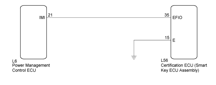
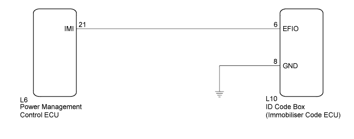
WIRING DIAGRAM
-
w/ Wireless Buzzer Answer-back Function
-
w/o Wireless Buzzer Answer-back Function
INSPECTION PROCEDURE
Note
If the ID code box (immobiliser code ECU)*1 or certification ECU (smart key ECU assembly)*2 is replaced, refer to the Service Bulletin.
-
*1: w/o Wireless Buzzer Answer-back Function
-
*2: w/ Wireless Buzzer Answer-back Function
PROCEDURE
-
CHECK DTC OUTPUT
-
Clear the DTCs Click here.
-
Recheck for DTCs Click here.
Tech Tips
If any DTCs other than DTC B279A are output, troubleshoot those DTCs first.
Result Result Proceed to DTC B279A is output A DTC B279A and other DTCs are output B
B 
GO TO DIAGNOSTIC TROUBLE CODE CHART Click here
A 
-
-
SYSTEM CHECK
-
Check the vehicle specification.
Result Result Proceed to w/ Wireless Buzzer Answer-back Function A w/o Wireless Buzzer Answer-back Function B
B 
CHECK HARNESS AND CONNECTOR (ID CODE BOX - POWER MANAGEMENT CONTROL ECU) Click here
A
-
-
CHECK HARNESS AND CONNECTOR (CERTIFICATION ECU - POWER MANAGEMENT CONTROL ECU)
-
Disconnect the L56 certification ECU (smart key ECU assembly) connector.
-
Disconnect the L6 power management control ECU connector.
-
Measure the resistance and voltage according to the value(s) in the table below.
Standard Resistance Tester Connection Condition Specified Condition L52-35 (EFIO) - L6-21 (IMI) Always Below 1 Ω L6-21 (IMI) - Body ground Always 10 kΩ or higher Standard Voltage Tester Connection Condition Specified Condition L6-21 (IMI) - Body ground Always Below 1 V
NG
REPAIR OR REPLACE HARNESS OR CONNECTOR
OK
-
-
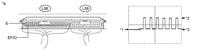
CHECK CERTIFICATION ECU (SMART KEY ECU ASSEMBLY) (WAVEFORM)
-
Reconnect the L56 certification ECU (smart key ECU assembly) connector.
-
Reconnect the L6 power management control ECU connector.
-
Using an oscilloscope, check the waveform.
Waveform (Reference) Item Content Terminal No. (Symbol) L56-35 (EFIO) - L56-15 (E) Tool Setting 5 V/DIV., 50 msec./DIV. Condition Power switch on (IG) OK Waveform is output normally (see illustration). Text in Illustration *1 GND *2 HIGH *3 LOW - - *a Component with harness connected
(Certification ECU (Smart Key ECU Assembly))
- -
NG
REPLACE CERTIFICATION ECU (SMART KEY ECU ASSEMBLY) Click here
OK 
REPLACE POWER MANAGEMENT CONTROL ECU Click here
-
-
REPLACE CERTIFICATION ECU (SMART KEY ECU ASSEMBLY)
-
Replace the certification ECU (smart key ECU assembly).
Tech Tips
refer to the Service Bulletin.
NEXT
-
-
KEY REGISTRATION
-
Register the key.
Tech Tips
refer to the Service Bulletin.
NEXT
-
-
ECU COMMUNICATION ID REGISTRATION
-
Register the ECU communication ID.
Tech Tips
refer to the Service Bulletin.
NEXT
-
-
CHECK DTC OUTPUT
-
Clear the DTCs Click here.
-
Recheck for DTCs Click here.
OK DTC B279A is not output.
NG
REPLACE POWER MANAGEMENT CONTROL ECU Click here
OK
END (CERTIFICATION ECU (SMART KEY ECU ASSEMBLY) WAS DEFECTIVE)
-
-
CHECK HARNESS AND CONNECTOR (ID CODE BOX - POWER MANAGEMENT CONTROL ECU)
-
Disconnect the L10 ID code box (immobiliser code ECU) connector.
-
Disconnect the L6 power management control ECU connector.
-
Measure the resistance and voltage according to the value(s) in the table below.
Standard Resistance Tester Connection Condition Specified Condition L10-6 (EFIO) - L6-21 (IMI) Always Below 1 Ω L6-21 (IMI) - Body ground Always 10 kΩ or higher Standard Voltage Tester Connection Condition Specified Condition L6-21 (IMI) - Body ground Always Below 1 V
NG
REPAIR OR REPLACE HARNESS OR CONNECTOR
OK
-
-
CHECK ID CODE BOX (IMMOBILISER CODE ECU) (WAVEFORM)
-
Reconnect the L10 ID code box (immobiliser code ECU) connector.
-
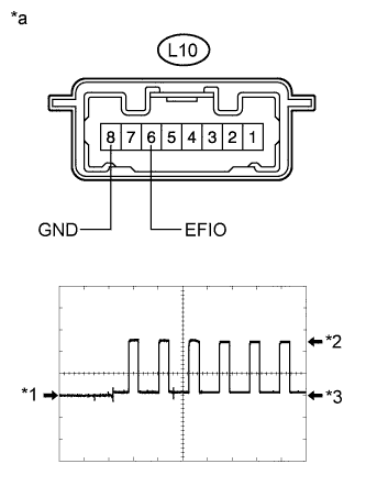
Text in Illustration *1 GND *2 HIGH *3 LOW *a Component with harness connected
(ID Code Box (Immobiliser Code ECU))
Reconnect the L6 power management control ECU connector.
-
Using an oscilloscope, check the waveform.
Waveform (Reference) Item Content Terminal No. (Symbol) L10-6 (EFIO) - L10-8 (GND) Tool Setting 5 V/DIV., 50 msec./DIV. Condition Power switch on (IG) OK Waveform is output normally (see illustration).
NG
REPLACE ID CODE BOX (IMMOBILISER CODE ECU) Click here
OK
REPLACE POWER MANAGEMENT CONTROL ECU Click here
-
-
REPLACE ID CODE BOX (IMMOBILISER CODE ECU)
-
Replace the ID code box (immobiliser code ECU).
Tech Tips
refer to the Service Bulletin.
NEXT
-
-
ECU CODE REGISTRATION
-
Register the ECU code.
Tech Tips
refer to the Service Bulletin.
NEXT
-
-
ECU COMMUNICATION ID REGISTRATION
-
Register the ECU communication ID.
Tech Tips
refer to the Service Bulletin.
NEXT
-
-
CHECK DTC OUTPUT
-
Clear the DTCs Click here.
-
Recheck for DTCs Click here.
OK DTC B279A is not output.
NG
REPLACE POWER MANAGEMENT CONTROL ECU Click here
OK
END (ID CODE BOX (IMMOBILISER CODE ECU) WAS DEFECTIVE)
-