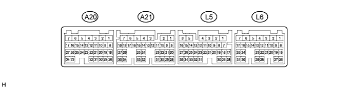
ENGINE IMMOBILISER SYSTEM TERMINALS OF ECU
-
CHECK POWER SWITCH
-
Disconnect the L33 power switch connector.

-
Measure the resistance according to the value(s) in the table below.
Tech Tips
Measure the values on the wire harness side with the connector disconnected.
Tester Connection Wiring Color Terminal Description Condition Specified Condition L33-8 (AGND) - Body ground P - Body ground Ground Always Below 1 Ω If the result is not as specified, there may be a malfunction in the wire harness.
-
Reconnect the L33 power switch connector.
-
Measure the voltage and check for pulses according to the value(s) in the table below.
Tester Connection Wiring Color Terminal Description Condition Specified Condition L33-9 (TXCT) - L33-8 (AGND) V - P Key code output signal
-
Power switch off
-
30 seconds after door opened and closed
-
Brake pedal not depressed
Below 1 V L33-9 (TXCT) - L33-8 (AGND) V - P Key code output signal
-
Power switch off
-
Key not in cabin
-
Within 30 seconds after power switch pressed
Pulse generation
(See waveform 1)
L33-10 (CODE) - L33-8 (AGND) L - P Demodulated signal of key code data
-
Power switch off
-
30 seconds after door opened and closed
-
Brake pedal not depressed
Below 1 V L33-10 (CODE) - L33-8 (AGND) L - P Demodulated signal of key code data
-
Power switch off
-
Key battery removed
-
Power switch touched with key and then pressed
Pulse generation
(See waveform 2)
L33-14 (VC5) - L33-8 (AGND) Y - P Power supply
-
Power switch off
-
30 seconds after door opened and closed
-
Brake pedal not depressed
Below 1 V L33-14 (VC5) - L33-8 (AGND) Y - P Power supply
-
Power switch off
-
Key not in cabin
-
Within 30 seconds after power switch pressed
Pulse generation
(See waveform 3)
If the result is not as specified, the power switch may have a malfunction.
-
-
Inspect using an oscilloscope.
-
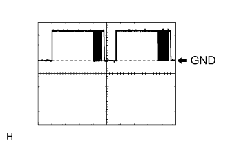
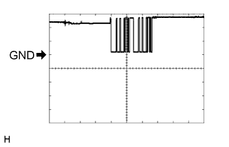
Waveform 1 (Reference)
Item Content Tester Connection L33-9 (TXCT) - L33-8 (AGND) Tool Setting 2 V/DIV., 50 ms./DIV. Condition
-
Power switch off
-
Key not in cabin
-
Within 30 seconds after power switch pressed
-
-
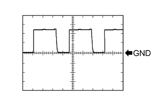
Waveform 2 (Reference)
Item Content Tester Connection L33-10 (CODE) - L33-8 (AGND) Tool Setting 2 V/DIV., 50 ms./DIV. Condition
-
Power switch off
-
Key battery removed
-
Power switch touched with key and then pressed
-
-
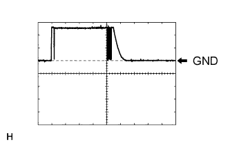
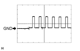
Waveform 3 (Reference)
Item Content Tester Connection L33-14 (VC5) - L33-8 (AGND) Tool Setting 2 V/DIV., 200 ms./DIV. Condition
-
Power switch off
-
Key not in cabin
-
Within 30 seconds after power switch pressed
-
-
-
-
CHECK CERTIFICATION ECU (SMART KEY ECU ASSEMBLY)
-
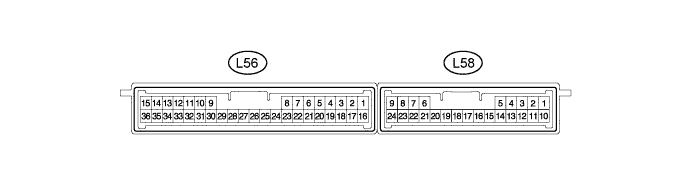
Disconnect the L56 certification ECU (smart key ECU assembly) connector.
-
Measure the resistance and voltage according to the value(s) in the table below.
Tech Tips
Measure the values on the wire harness side with the connector disconnected.
Tester Connection Wiring Color Terminal Description Condition Specified Condition L56-1 (+B) - L56-15 (E) B - W-B +B power supply Power switch off 11 to 14 V L56-15 (E) - Body ground W-B - Body ground Ground Always Below 1 Ω L56-17 (CUTB) - L56-15 (E) Y - W-B Dark current cut fuse pin input signal Power switch off 11 to 14 V If the result is not as specified, there may be a malfunction in the wire harness.
-
Reconnect the L56 certification ECU (smart key ECU assembly) connector.
-
Measure the resistance and voltage according to the value(s) in the table below.
Tester Connection Wiring Color Terminal Description Condition Specified Condition L56-2 (IND) - Body ground B - Body ground Security indicator light signal
-
Power switch on (IG)
-
Security indicator light off
Below 2 V L56-2 (IND) - Body ground B - Body ground Security indicator light signal
-
Power switch off
-
Security indicator light blinks
Pulse generation L56-12 (TXCT) - L56-36 (AGND) V - P Power switch TXCT output
-
Power switch off
-
30 seconds after door opened and closed
-
Brake pedal not depressed
Below 1 V L56-12 (TXCT) - L56-36 (AGND) V - P Power switch TXCT output
-
Power switch off
-
Key not in cabin
-
Power switch pressed within 30 seconds
Pulse generation (See waveform 1) L56-13 (CODE) - L56-36 (AGND) L - P Power switch CODE input
-
Power switch off
-
30 seconds after door opened and closed
-
Brake pedal not depressed
Below 1 V L56-13 (CODE) - L56-36 (AGND) L - P Power switch CODE input
-
Power switch off
-
Key battery removed
-
Power switch touched with key and pressed
Pulse generation (See waveform 2) L56-16 (IG) - L56-15 (E) BE - W-B IG power supply Power switch off Below 1 V L56-16 (IG) - L56-15 (E) BE - W-B IG power supply Power switch on (IG) 11 to 14 V L56-28 (VC5) - L56-36 (AGND) Y - P Power switch power supply
-
Power switch off
-
30 seconds after door opened and closed
-
Brake pedal not depressed
Below 1 V L56-28 (VC5) - L56-36 (AGND) Y - P Power switch power supply
-
Power switch off
-
Key not in cabin
-
Power switch pressed within 30 seconds
Pulse generation (See waveform 3) L56-34 (EFII) - L56-15 (E) L - W-B Power management control ECU output signal Power switch off 11 to 14 V L56-34 (EFII) - L56-15 (E) L - W-B Power management control ECU output signal Within 3 seconds after power switch on (READY), or within 3 seconds after power switch first turned on (IG) after auxiliary battery disconnected and connected Pulse generation (See waveform 4) L56-35 (EFIO) - L56-15 (E) R - W-B Power management control ECU input signal Power switch off Below 1 V L56-35 (EFIO) - L56-15 (E) R - W-B Power management control ECU input signal Within 3 seconds after power switch on (READY), or within 3 seconds after power switch first turned on (IG) after auxiliary battery disconnected and connected Pulse generation (See waveform 5) L56-36 (AGND) - Body ground P - Body ground Power switch ground Always Below 1 Ω
-
If the result is not as specified, the certification ECU (smart key ECU assembly) may have a malfunction.
-
-
Inspect using an oscilloscope.
-
Waveform 1 (Reference)
Item Content Tester Connection L56-12 (TXCT) - L56-36 (AGND) Tool Setting 2 V/DIV., 50 ms./DIV. Condition
-
Power switch off
-
Key not in cabin
-
Power switch pressed within 30 seconds
-
-
Waveform 2 (Reference)
Item Content Tester Connection L56-13 (CODE) - L56-36 (AGND) Tool Setting 2 V/DIV., 50 ms./DIV. Condition
-
Power switch off
-
Key battery removed
-
Power switch touched with key and pressed
-
-
Waveform 3 (Reference)
Item Content Tester Connection L56-28 (VC5) - L56-36 (AGND) Tool Setting 2 V/DIV., 200 ms./DIV. Condition
-
Power switch off
-
Key not in cabin
-
Power switch pressed within 30 seconds
-
-
Waveform 4 (Reference)
Item Content Tester Connection L56-34 (EFII) - L56-15 (E) Tool Setting 5 V/DIV., 500 ms./DIV. Condition Within 3 seconds after power switch on (READY), or within 3 seconds after power switch first turned on (IG) after auxiliary battery disconnected and connected -
Waveform 5 (Reference)
Item Content Tester Connection L56-35 (EFIO) - L56-15 (E) Tool Setting 5 V/DIV., 50 ms./DIV. Condition Within 3 seconds after power switch on (READY), or within 3 seconds after power switch first turned on (IG) after auxiliary battery disconnected and connected
-
-
-
CHECK ID CODE BOX (IMMOBILISER CODE ECU)
-
Disconnect the L10 ID code box (immobiliser code ECU) connector.

-
Measure the resistance and voltage according to the value(s) in the table below.
Tech Tips
Measure the values on the wire harness side with the connector disconnected.
Tester Connection Wiring Color Terminal Description Condition Specified Condition L10-1 (+B) - L10-8 (GND) B - W-B +B power supply Power switch off 11 to 14 V L10-8 (GND) - Body ground W-B - Body ground Ground Always Below 1 Ω
-
If the result is not as specified, there may be a malfunction in the wire harness.
-
-
Reconnect the L10 ID code box (immobiliser code ECU) connector.
-
Measure the voltage according to the value(s) in the table below.
Tester Connection Wiring Color Terminal Description Condition Specified Condition L10-5 (EFII) - L10-8 (GND) L - W-B Power management control ECU output signal Power switch off 11 to 14 V L10-5 (EFII) - L10-8 (GND) L - W-B Power management control ECU output signal Within 3 seconds after power switch on (READY), or within 3 seconds after power switch first turned on (IG) after auxiliary battery disconnected and connected Pulse generation
(See waveform 1)
L10-6 (EFIO) - L10-8 (GND) R - W-B Power management control ECU input signal Power switch off Below 1 V L10-6 (EFIO) - L10-8 (GND) R - W-B Power management control ECU input signal Within 3 seconds after power switch on (READY), or within 3 seconds after power switch first turned on (IG) after auxiliary battery disconnected and connected Pulse generation
(See waveform 2)
-
If the result is not as specified, the ID code box (immobiliser code ECU) may have a malfunction.
-
-
Inspect using an oscilloscope.
-
Waveform 1 (Reference)
Item Content Tester Connection L10-5 (EFII) - L10-8 (GND) Tool Setting 5 V/DIV., 500 ms./DIV. Condition Within 3 seconds after power switch on (READY), or within 3 seconds after power switch first turned on (IG) after auxiliary battery disconnected and connected -
Waveform 2 (Reference)
Item Content Tester Connection L10-6 (EFIO) - L10-8 (GND) Tool Setting 5 V/DIV., 50 ms./DIV. Condition Within 3 seconds after power switch on (READY), or within 3 seconds after power switch first turned on (IG) after auxiliary battery disconnected and connected
-
-
-
CHECK TRANSMISSION CONTROL ECU ASSEMBLY
-
Disconnect the A23 and A22 transmission control ECU assembly connectors.

-
Measure the voltage and resistance according to the value(s) in the table below.
Tech Tips
Measure the values on the wire harness side with the connectors disconnected.
Tester Connection Wiring Color Terminal Description Condition Specified Condition A22-15 (BATT) - Body ground SB - Body ground BATT power supply Power switch off 11 to 14 V A23-1 (E1) - Body ground BR - Body ground Ground Always Below 1 Ω A23-5 (E02) - Body ground W-B - Body ground Ground Always Below 1 Ω A23-6 (E01) - Body ground W-B - Body ground Ground Always Below 1 Ω If the result is not as specified, there may be a malfunction in the wire harness.
-
-
CHECK POWER MANAGEMENT CONTROL ECU
-
Disconnect the L5 power management control ECU connector.
-
Measure the resistance according to the value(s) in the table below.
Tech Tips
Measure the values on the wire harness side with the connector disconnected.
Tester Connection Wiring Color Terminal Description Condition Specified Condition L5-6 (E1) - Body ground BR - Body ground Ground Always Below 1 Ω If the result is not as specified, there may be a malfunction in the wire harness.
-
Reconnect the L5 power management control ECU connector.
-
Measure the voltage according to the value(s) in the table below.
Tester Connection Wiring Color Terminal Description Condition Specified Condition L6-20 (IMO) - L5-6 (E1) L - BR ID code box (immobiliser code ECU) input signal Power switch off 11 to 14 V L6-20 (IMO) - L5-6 (E1) L - BR ID code box (immobiliser code ECU) input signal Within 3 seconds after power switch on (READY), or within 3 seconds after power switch first turned on (IG) after auxiliary battery disconnected and connected Pulse generation
(See waveform 1)
L6-21 (IMI) - L5-6 (E1) R - BR ID code box (immobiliser code ECU) output signal Power switch off Below 1 V L6-21 (IMI) - L5-6 (E1) R - BR ID code box (immobiliser code ECU) output signal Within 3 seconds after power switch on (READY), or within 3 seconds after power switch first turned on (IG) after auxiliary battery disconnected and connected Pulse generation
(See waveform 2)
-
If the result is not as specified, the power management control ECU may have a malfunction.
-
-
Waveform:
-
Waveform 1 (Reference)
Item Content Tester Connection L6-20 (IMO) - L5-6 (E1) Tool Setting 5 V/DIV., 500 ms./DIV. Condition Within 3 seconds after power switch on (READY), or within 3 seconds after power switch first turned on (IG) after auxiliary battery disconnected and connected -
Waveform 2 (Reference)
Item Content Tester Connection L6-21 (IMI) - L5-6 (E1) Tool Setting 5 V/DIV., 50 ms./DIV. Condition Within 3 seconds after power switch on (READY), or within 3 seconds after power switch first turned on (IG) after auxiliary battery disconnected and connected
-
-
-
COMBINATION METER ASSEMBLY
-
Disconnect the L23 combination meter assembly connector.

-
Measure the voltage and resistance according to the value(s) in the table below.
Tech Tips
Measure the values on the wire harness side with the connector disconnected.
Tester Connection Wiring Color Terminal Description Condition Specified Condition L23-18 (B) - Body ground R - Body ground B power supply Power switch off 11 to 14 V L23-30 (ES) - Body ground BR - Body ground Ground (Signal ground) Always Below 1 Ω If the result is not as specified, there may be a malfunction in the wire harness.
-
Reconnect the L23 combination meter assembly connector.
-
Measure the voltage and check for pulses according to the value(s) in the table below.
Tester Connection Wiring Color Terminal Description Condition Specified Condition L23-19 (IG+) - Body ground L - Body ground Power switch signal Power switch off Below 1 V L23-19 (IG+) - Body ground L - Body ground Power switch signal Power switch on (IG) 11 to 14 V L23-22 (LP) - Body ground B - Body ground Security indicator light signal
-
Power switch on (IG)
-
Security indicator light off
Below 2 V L23-22 (LP) - Body ground B - Body ground Security indicator light signal
-
Power switch off
-
Security indicator light blinks
Pulse generation If the result is not as specified, the combination meter assembly may have a malfunction.
-
-