CAN COMMUNICATION SYSTEM TERMINALS OF ECU
Note
-
Turn the power switch off before measuring the resistances between CAN main bus wires and between CAN main bus branch wires.
-
Turn the power switch off before inspecting CAN bus wires for a ground short.
-
After the power switch is turned off, check that the key reminder warning system and light reminder warning system are not operating.
-
Before measuring the resistance, leave the vehicle as is for at least 1 minute and do not operate the power switch, any other switches or the doors. If any doors need to be opened in order to check connectors, open the doors and leave them open.
-
This section describes the standard CAN values for all CAN related components.
Tech Tips
-
Operating the power switch, any other switches or a door triggers related ECU and sensor communication on the CAN. This communication will cause the resistance value to change.
-
Even after DTCs are cleared, if a DTC is stored again after driving the vehicle for a while, the malfunction may be occurring due to vibration of the vehicle. In such a case, wiggling the ECUs or wire harness while performing the inspection below may help determine the cause of the malfunction.
-
CAN NO. 1 JUNCTION CONNECTOR (for LHD)
-
Check the CAN No. 1 junction connector.
-
Connection diagram
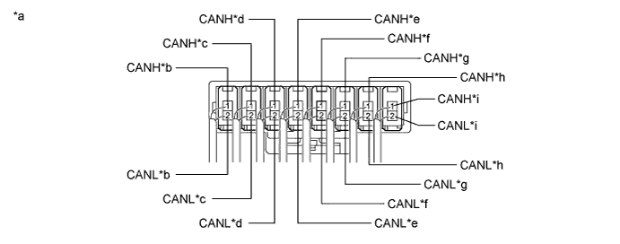
Text in Illustration *a Component with harness connected
(CAN No. 1 Junction Connector)
*b to CAN No. 2 Junction Connector *c to Main Body ECU *d to Steering Angle Sensor *e to Combination Meter Assembly *f to Power Steering ECU Assembly *g to Brake Booster with Master Cylinder (Skid Control ECU) *h to DLC3 *i to ECM - -
-
-
Check the connection diagram of the components which are connected to the CAN No. 1 junction connector.
Terminal No. (Symbol) Wiring Color Connected to L90-1 (CANH) P ECM L90-2 (CANL) V L91-1 (CANH) W DLC3 L91-2 (CANL) Y L92-1 (CANH) LG Brake booster with master cylinder (Skid control ECU) L92-2 (CANL) L L93-1 (CANH) R Power steering ECU assembly L93-2 (CANL) W L94-1 (CANH) P Combination meter assembly L94-2 (CANL) W L95-1 (CANH) L Steering angle sensor L95-2 (CANL) W L96-1 (CANH) BR Main body ECU L96-2 (CANL) W L97-1 (CANH) V CAN No. 2 junction connector L97-2 (CANL) W
-
-
CAN NO. 1 JUNCTION CONNECTOR (for RHD)
-
Check the CAN No. 1 junction connector.
-
Connection diagram
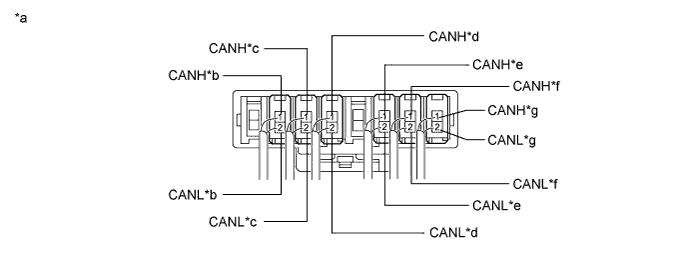
Text in Illustration *a Component with harness connected
(CAN No. 1 Junction Connector)
*b to Power Management Control ECU *c to Yaw Rate and Acceleration Sensor *d to CAN No. 2 Junction Connector *e to Main Body ECU *f to Combination Meter Assembly *g to ECM - -
-
-
Check the connection diagram of the components which are connected to the CAN No. 1 junction connector.
Terminal No. (Symbol) Wiring Color Connected to L90-1 (CANH) P ECM L90-2 (CANL) V L94-1 (CANH) P Combination meter assembly L94-2 (CANL) W L96-1 (CANH) BR Main body ECU L96-2 (CANL) W L97-1 (CANH) V CAN No. 2 junction connector L97-2 (CANL) W L100-1 (CANH) W Yaw rate and acceleration sensor L100-2 (CANL) Y L102-1 (CANH) B Power management control ECU L102-2 (CANL) W
-
-
CAN NO. 2 JUNCTION CONNECTOR (for LHD)
-
Check the CAN No. 2 junction connector.
-
Connection diagram
Text in Illustration *a Component with harness connected
(CAN No. 2 Junction Connector)
*b to CAN No. 1 Junction Connector *c to Power Management Control ECU *d to Plugin Charge Control ECU Assembly *e to Yaw Rate and Acceleration Sensor *f to Certification ECU (Smart Key ECU Assembly) *g
-
to Navigation ECU Sub-assembly (Navigation Receiver Assembly)*1
-
to Radio and Display Receiver Assembly*2
- - -
-
-
Check the connection diagram of the components which are connected to the CAN No. 2 junction connector.
Terminal No. (Symbol) Wiring Color Connected to L98-1 (CANH) G
-
Navigation ECU sub-assembly (Navigation receiver assembly)*1
-
Radio and display receiver assembly*2
L98-2 (CANL) W L99-1 (CANH) BE Certification ECU (Smart key ECU assembly) L99-2 (CANL) P L100-1 (CANH) Y Yaw rate and acceleration sensor L100-2 (CANL) L L101-1 (CANH) B Plugin charge control ECU assembly L101-2 (CANL) W L102-1 (CANH) B Power management control ECU L102-2 (CANL) W L103-1 (CANH) V CAN No. 1 junction connector L103-2 (CANL) W *1: for Navigation receiver type
*2: for Radio and display type
-
-
-
CAN NO. 2 JUNCTION CONNECTOR (for RHD)
-
Check the CAN No. 2 junction connector.
-
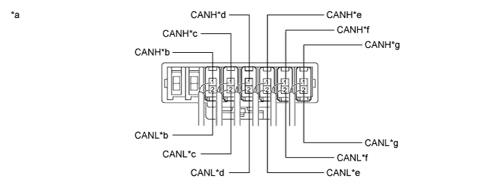
Connection diagram
Text in Illustration *a Component with harness connected
(CAN No. 2 Junction Connector)
*b to CAN No. 1 Junction Connector *c to Plugin Charge Control ECU Assembly *d to Certification ECU (Smart Key ECU Assembly) *e
-
to Navigation ECU Sub-assembly (Navigation Receiver Assembly)*1
-
to Radio and Display Receiver Assembly*2
*f to Steering Angle Sensor *g to Power Steering ECU Assembly *h to Brake Booster with Master Cylinder (Skid Control ECU) *i DLC3 - - -
-
-
Check the connection diagram of the components which are connected to the CAN No. 2 junction connector.
Terminal No. (Symbol) Wiring Color Connected to L91-1 (CANH) W DLC3 L91-2 (CANL) Y L92-1 (CANH) LG Brake booster with master cylinder (Skid control ECU) L92-2 (CANL) L L93-1 (CANH) R Power steering ECU assembly L93-2 (CANL) W L95-1 (CANH) L Steering angle sensor L95-2 (CANL) W L98-1 (CANH) G
-
Navigation ECU sub-assembly (Navigation receiver assembly)*1
-
Radio and display receiver assembly*2
L98-2 (CANL) W L99-1 (CANH) BE Certification ECU (Smart key ECU assembly) L99-2 (CANL) P L101-1 (CANH) B Plugin charge control ECU assembly L101-2 (CANL) W L103-1 (CANH) V CAN No. 1 junction connector L103-2 (CANL) W *1: for Navigation receiver type
*2: for Radio and display type
-
-
-
CAN NO. 3 JUNCTION CONNECTOR (for LHD)
-
Check the CAN No. 3 junction connector.
-
Connection diagram
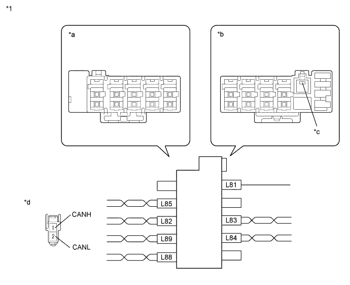
Text in Illustration *1 CAN No. 3 Junction Connector - - *a Junction Connector B Side *b Junction Connector A Side *c Earth Terminal *d Front view of wire harness connector
(to CAN No. 3 Junction Connector)
-
-
Check the connection diagram of the components which are connected to the CAN No. 3 junction connector.
Terminal No. (Symbol) Wiring Color Connected to L81 W-B Body ground L82-1 (CANH) V CAN No. 5 junction connector L82-2 (CANL) W L83-1 (CANH) LG Seat belt control ECU*1 L83-2 (CANL) L L84-1 (CANH) B Driving support ECU*2 L84-2 (CANL) W L85-1 (CANH) Y Parking assist ECU*3 L85-2 (CANL) W L88-1 (CANH) R Center airbag sensor assembly L88-2 (CANL) G L89-1 (CANH) Y Air conditioning amplifier assembly L89-2 (CANL) BR
-
*1: w/ Pre-crash safety system
-
*2: w/ Dynamic radar cruise control system
-
*3: w/ Intelligent parking assist system
-
-
-
CAN NO. 3 JUNCTION CONNECTOR (for RHD)
-
Check the CAN No. 3 junction connector.
-
Connection diagram
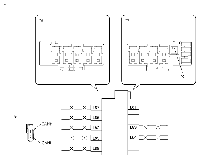
Text in Illustration *1 CAN No. 3 Junction Connector - - *a Junction Connector B Side *b Junction Connector A Side *c Earth Terminal *d Front view of wire harness connector
(to CAN No. 3 Junction Connector)
-
-
Check the connection diagram of the components which are connected to the CAN No. 3 junction connector.
Terminal No. (Symbol) Wiring Color Connected to L81 W-B Body ground L82-1 (CANH) P Power management control ECU L82-2 (CANL) V L83-1 (CANH) LG Seat belt control ECU*1 L83-2 (CANL) L L84-1 (CANH) B Driving support ECU*2 L84-2 (CANL) W L85-1 (CANH) Y Parking assist ECU*3 L85-2 (CANL) W L87-1 (CANH) BE Transmission control ECU assembly L87-2 (CANL) P L88-1 (CANH) R Center airbag sensor assembly L88-2 (CANL) G L89-1 (CANH) Y Air conditioning amplifier assembly L89-2 (CANL) BR
-
*1: w/ Pre-crash safety system
-
*2: w/ Dynamic radar cruise control system
-
*3: w/ Intelligent parking assist system
-
-
-
CAN NO. 4 JUNCTION CONNECTOR
-
Check the CAN No. 4 junction connector.
-
Connection diagram
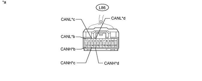
Text in Illustration *a Front view of wire harness connector
(to CAN No. 4 Junction Connector)
*b to Power Management Control ECU *c to Brake Booster with Master Cylinder (Skid Control ECU) *d to ECM
-
-
Check the connection diagram of the components which are connected to the CAN No. 4 junction connector.
Terminal No. (Symbol) Wiring Color Connected to L86-12 (CANH) LG Power management control ECU L86-1 (CANL) L L86-14 (CANH) P Brake booster with master cylinder (Skid control ECU) L86-3 (CANL) V L86-15 (CANH) B ECM L86-4 (CANL) W
-
-
CAN NO. 5 JUNCTION CONNECTOR (for LHD)
-
Check the CAN No. 5 junction connector.
-
Connection diagram
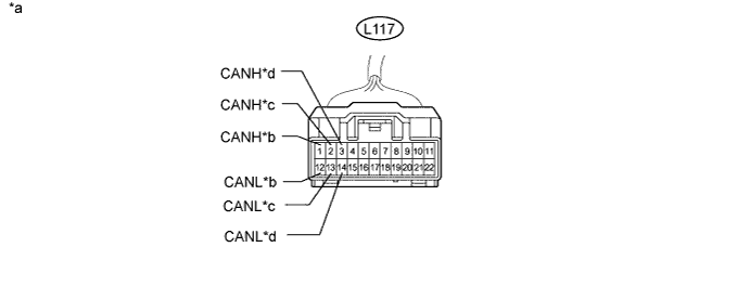
Text in Illustration *a Front view of wire harness connector
(to CAN No. 5 Junction Connector)
*b to Transmission Control ECU Assembly *c to Power Management Control ECU *d to CAN No. 3 Junction Connector
-
-
Check the connection diagram of the components which are connected to the CAN No. 5 junction connector.
Terminal No. (Symbol) Wiring Color Connected to L117-1 (CANH) BE Transmission control ECU assembly L117-12 (CANL) P L117-2 (CANH) P Power management control ECU L117-13 (CANL) V L117-3 (CANH) V CAN No. 3 junction connector L117-14 (CANL) W
-
-
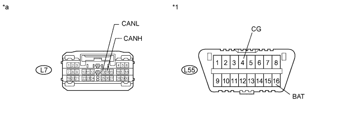
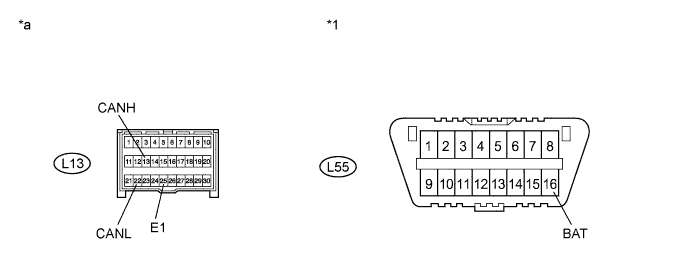
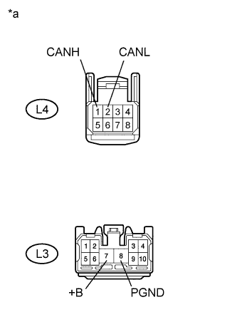
DLC3
-
Disconnect the cable from the negative (-) auxiliary battery terminal.
-
Measure the resistance according to the value(s) in the table below.
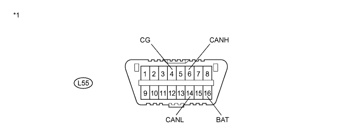
Text in Illustration *1 DLC3 - -
-
-
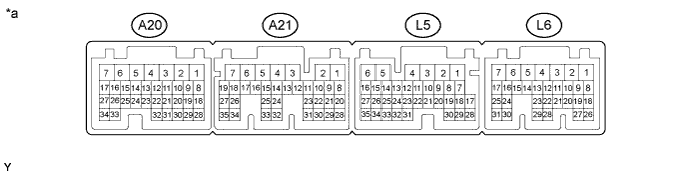
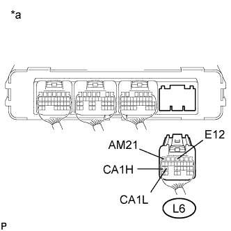
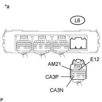
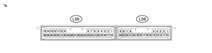
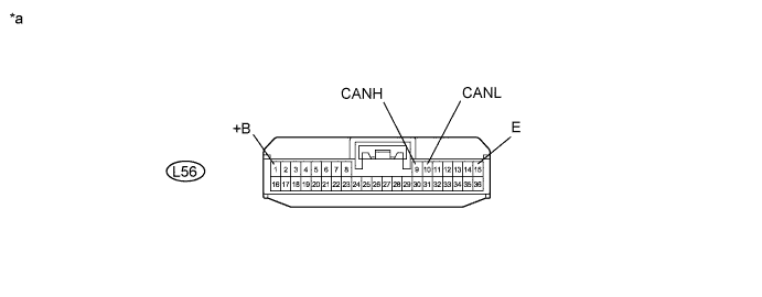
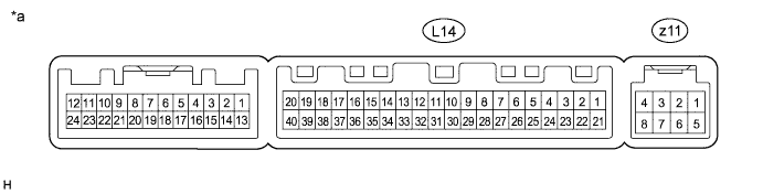
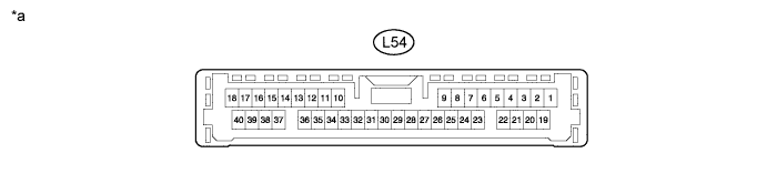
ECM
Text in Illustration *a Component without harness connected
(ECM)
- -
-
Disconnect the cable from the negative (-) auxiliary battery terminal.
-
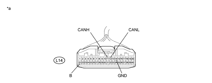
Disconnect the ECM connectors.
Text in Illustration *a Front view of wire harness connector
(to ECM)
- - -
Measure the resistance according to the value(s) in the table below.
-
-
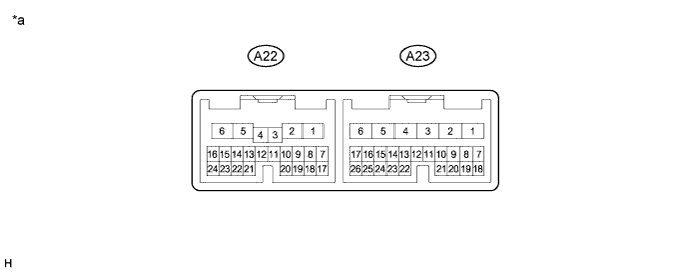
COMBINATION METER ASSEMBLY
Text in Illustration *a Component without harness connected
(Combination Meter Assembly)
- -
-
Disconnect the cable from the negative (-) auxiliary battery terminal.
-
Disconnect the combination meter assembly connector.
Text in Illustration *a Front view of wire harness connector
(to Combination Meter Assembly)
- - -
Measure the resistance according to the value(s) in the table below.
-
-
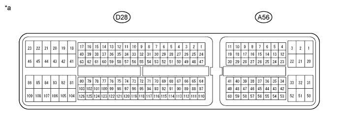
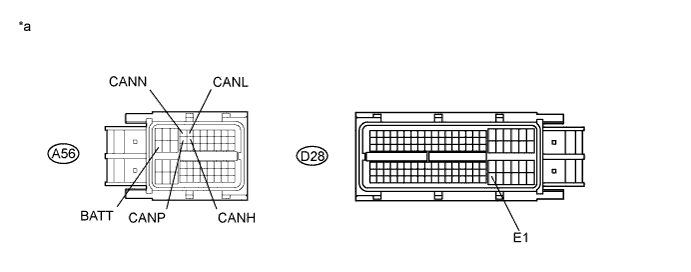
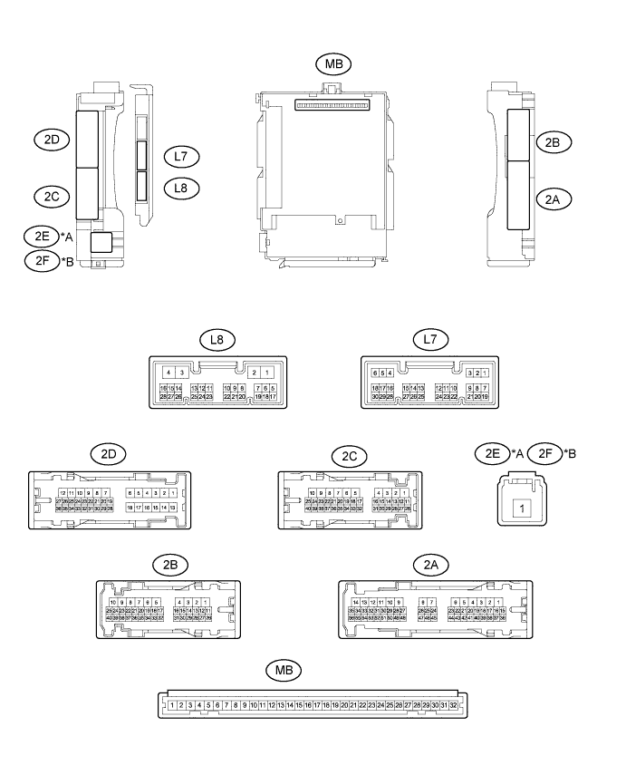
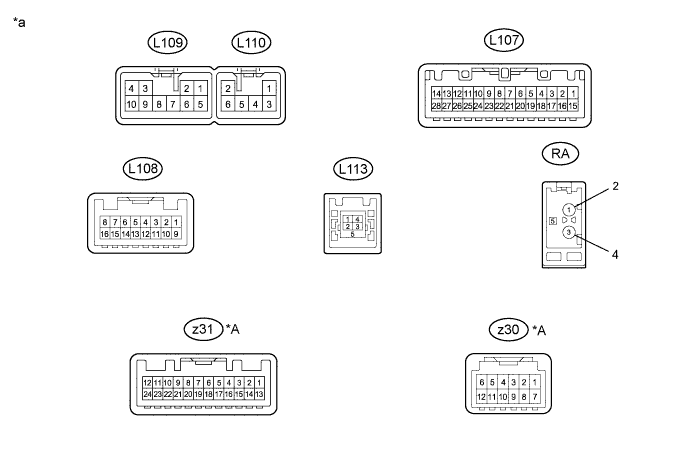
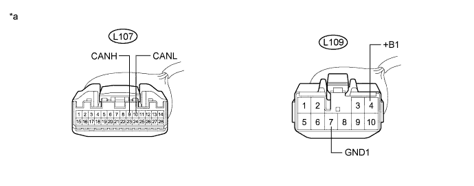
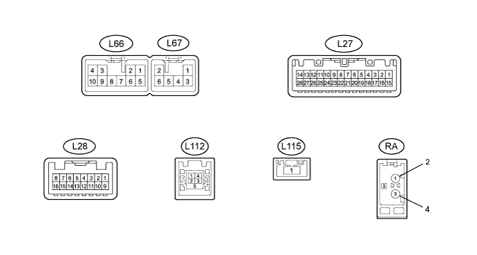
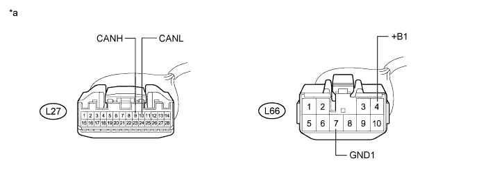
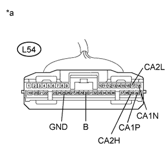
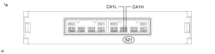
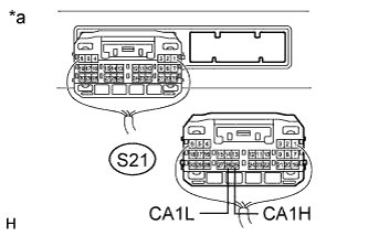
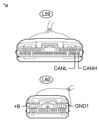
POWER MANAGEMENT CONTROL ECU
Text in Illustration *a Component without harness connected
(Power Management Control ECU)
- -
-
V1 Bus Branch Wire
-
Disconnect the cable from the negative (-) auxiliary battery terminal.
-
Text in Illustration *a Rear view of wire harness connector
(to Power Management Control ECU)
Disconnect the power management control ECU connector.
-
Measure the resistance according to the value(s) in the table below.
-
-
V2 Bus Main Wire
-
Disconnect the cable from the negative (-) auxiliary battery terminal.
-
Text in Illustration *a Rear view of wire harness connector
(to Power Management Control ECU)
Disconnect the power management control ECU connector.
-
Measure the resistance according to the value(s) in the table below.
-
-
Power Management Bus Main Wire
-
Disconnect the cable from the negative (-) auxiliary battery terminal.
-
Text in Illustration *a Rear view of wire harness connector
(to Power Management Control ECU)
Disconnect the power management control ECU connector.
-
Measure the resistance according to the value(s) in the table below.
-
-
-
MAIN BODY ECU
Text in Illustration *A for LHD *B for RHD *a Component without harness connected
(Instrument Panel Junction Block Assembly and Main Body ECU)
- -
-
Disconnect the cable from the negative (-) auxiliary battery terminal.
-
Disconnect the main body ECU connector.
Text in Illustration *1 DLC3 - - *a Front view of wire harness connector
(to Main Body ECU)
- - -
Measure the resistance according to the value(s) in the table below.
-
-
BRAKE BOOSTER WITH MASTER CYLINDER (SKID CONTROL ECU)
Text in Illustration *a Component without harness connected
(Brake Booster with Master Cylinder (Skid Control ECU))
- -
-
Disconnect the cable from the negative (-) auxiliary battery terminal.
-
Text in Illustration *a Front view of wire harness connector
(to Brake Booster with Master Cylinder (Skid Control ECU))
Disconnect the brake booster with master cylinder (skid control ECU) connector.
-
Measure the resistance according to the value(s) in the table below.
-
-
STEERING ANGLE SENSOR
-
Disconnect the cable from the negative (-) auxiliary battery terminal.
-
Text in Illustration *a Front view of wire harness connector
(to Steering Angle Sensor)
Disconnect the steering angle sensor connector.
-
Measure the resistance according to the value(s) in the table below.
-
-
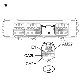
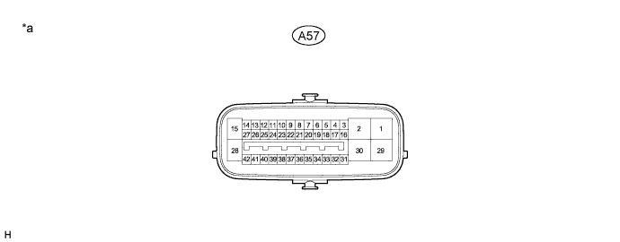
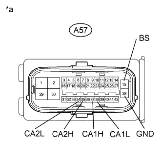
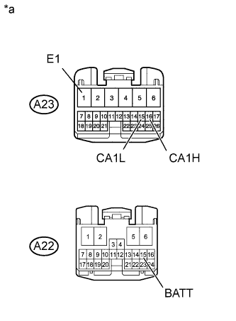
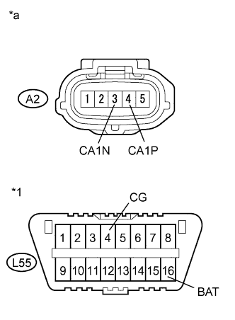
YAW RATE AND ACCELERATION SENSOR
-
Disconnect the cable from the negative (-) auxiliary battery terminal.
-
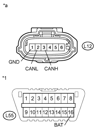
Text in Illustration *1 DLC3 *a Front view of wire harness connector
(to Yaw Rate and Acceleration Sensor)
Disconnect the yaw rate and acceleration sensor connector.
-
Measure the resistance according to the value(s) in the table below.
-
*1: for LHD
-
*2: for RHD
-
-
-
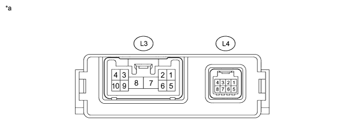
POWER STEERING ECU ASSEMBLY
Text in Illustration *a Component without harness connected
(Power Steering ECU Assembly)
- -
-
Disconnect the cable from the negative (-) auxiliary battery terminal.
-
Disconnect the power steering ECU assembly connectors.
Text in Illustration *a Front view of wire harness connector
(to Power Steering ECU Assembly)
- - -
Measure the resistance according to the value(s) in the table below.
-
-
CENTER AIRBAG SENSOR ASSEMBLY
-
Disconnect the cable from the negative (-) auxiliary battery terminal.
-
Disconnect the center airbag sensor assembly connector.
Text in Illustration *1 DLC3 - - *a Front view of wire harness connector
(to Center Airbag Sensor Assembly)
- - -
Measure the resistance according to the value(s) in the table below.
-
-
CERTIFICATION ECU (SMART KEY ECU ASSEMBLY)
Text in Illustration *a Component without harness connected
(Certification ECU (Smart Key ECU Assembly))
- -
-
Disconnect the cable from the negative (-) auxiliary battery terminal.
-
Disconnect the certification ECU (smart key ECU assembly) connector.
Text in Illustration *a Front view of wire harness connector
(to Certification ECU (Smart Key ECU Assembly))
- - -
Measure the resistance according to the value(s) in the table below.
-
-
TRANSMISSION CONTROL ECU ASSEMBLY
Text in Illustration *a Component without harness connected
(Transmission Control ECU Assembly)
- -
-
Disconnect the cable from the negative (-) auxiliary battery terminal.
-
Text in Illustration *a Front view of wire harness connector
(to Transmission Control ECU Assembly)
Disconnect the transmission control ECU assembly connectors.
-
Measure the resistance according to the value(s) in the table below.
-
-
RADIO AND DISPLAY RECEIVER ASSEMBLY (for Radio and Display Type)
Text in Illustration *A w/ Extension Module - - *a Component without harness connected
(Radio and Display Receiver Assembly)
- -
-
Disconnect the cable from the negative (-) auxiliary battery terminal.
-
Disconnect the radio and display receiver assembly connectors.
Text in Illustration *a Front view of wire harness connector
(to Radio and Display Receiver Assembly)
- -
-
Measure the resistance according to the value(s) in the table below.
-
-
-
NAVIGATION ECU SUB-ASSEMBLY (NAVIGATION RECEIVER ASSEMBLY) (for Navigation Receiver Type)
Text in Illustration *a Component without harness connected
(Navigation ECU Sub-assembly (Navigation Receiver Assembly))
- -
-
Disconnect the cable from the negative (-) auxiliary battery terminal.
-
Disconnect the navigation ECU sub-assembly (navigation receiver assembly) connectors.
Text in Illustration *a Front view of wire harness connector
(to Navigation ECU Sub-assembly (Navigation Receiver Assembly))
- -
-
Measure the resistance according to the value(s) in the table below.
-
-
-
AIR CONDITIONING AMPLIFIER ASSEMBLY
Text in Illustration *a Component without harness connected
(Air Conditioning Amplifier Assembly)
- -
-
Disconnect the cable from the negative (-) auxiliary battery terminal.
-
Disconnect the air conditioning amplifier assembly connector.
Text in Illustration *a Front view of wire harness connector
(to Air Conditioning Amplifier Assembly)
- - -
Measure the resistance according to the value(s) in the table below.
-
-
SEAT BELT CONTROL ECU (w/ Pre-crash Safety System)
Text in Illustration *a Component without harness connected
(Seat Belt Control ECU)
- -
-
Disconnect the cable from the negative (-) auxiliary battery terminal.
-
Text in Illustration *a Front view of wire harness connector
(to Seat Belt Control ECU)
Disconnect the seat belt control ECU connectors.
-
Measure the resistance according to the value(s) in the table below.
-
-
DRIVING SUPPORT ECU (w/ Dynamic Radar Cruise Control System)
Text in Illustration *a Component without harness connected
(Driving Support ECU)
- -
-
Disconnect the cable from the negative (-) auxiliary battery terminal.
-
Text in Illustration *a Front view of wire harness connector
(to Driving Support ECU)
Disconnect the driving support ECU connector.
-
Measure the resistance according to the value(s) in the table below.
-
-
MILLIMETER WAVE RADAR SENSOR ASSEMBLY (w/ Dynamic Radar Cruise Control System)
-
Disconnect the cable from the negative (-) auxiliary battery terminal.
-
Text in Illustration *1 DLC3 *a Front view of wire harness connector
(to Millimeter Wave Radar Sensor Assembly)
Disconnect the millimeter wave radar sensor assembly connector.
-
Measure the resistance according to the value(s) in the table below.
-
-
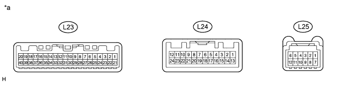
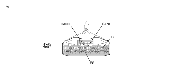
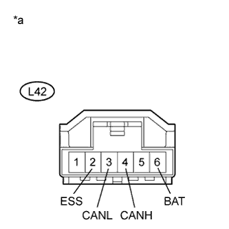
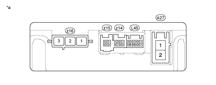
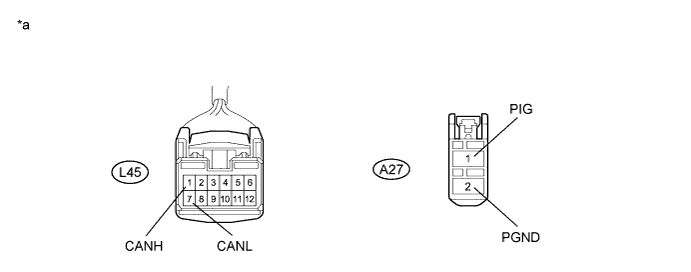
PLUGIN CHARGE CONTROL ECU ASSEMBLY
Text in Illustration *a Component without harness connected
(Plugin Charge Control ECU Assembly)
- -
-
Disconnect the cable from the negative (-) auxiliary battery terminal.
-
Text in Illustration *a Rear view of wire harness connector
(to Plugin Charge Control ECU Assembly)
Disconnect the plugin charge control ECU assembly connector.
-
Measure the resistance according to the value(s) in the table below.
-
-
PARKING ASSIST ECU (w/ Intelligent Parking Assist System)
-
Text in Illustration *a Front view of wire harness connector
(to Parking Assist ECU)
Disconnect the parking assist ECU connector.
-
Measure the resistance according to the value(s) in the table below.
-