POWER MANAGEMENT CONTROL ECU REMOVAL
-
PRECAUTION
Note
After turning the power switch off, waiting time may be required before disconnecting the cable from the negative (-) auxiliary battery terminal. Therefore, make sure to read the disconnecting the cable from the negative (-) auxiliary battery terminal notices before proceeding with work Click here.
-
WHEN REPLACING POWER MANAGEMENT CONTROL ECU
HV battery learning values are stored in the power management control ECU and ECM to display "HAVE TRACTION BATTERY INSPECTED" on the multi-information display. When either of these ECUs is replaced, the new ECU receives the HV battery learning value data from the other ECU and updates the information.
Note
-
Do not replace the power management control ECU and ECM at the same time as it clears the HV battery learning values. However, if it is necessary to replace both ECUs at the same time, replace them by following the procedure below.
-
Do not replace the power management control ECU or ECM with used ones from other vehicles.
-
Procedure when replacing both power management control ECU and ECM:
-
Disconnect the cable from the negative (-) auxiliary battery terminal.
-
Replace either of the ECUs.
-
Connect the cable to the negative (-) auxiliary battery terminal.
-
Turn the power switch on (READY) and wait for 5 minutes or more.
-
Turn the power switch off and disconnect the cable from the negative (-) auxiliary battery terminal.
-
Replace the other ECU.
-
Connect the cable to the negative (-) auxiliary battery terminal.
-
Check that the power switch can be turned on (READY).
Tech Tips
If the power management control ECU and ECM are replaced at the same time without following the above procedure, replace either of the ECUs with its original one and then replace it again by following the above procedure. If the correct procedure is not followed, perform the procedure again from the beginning.
-
-
-
REMOVE REAR NO. 3 FLOOR BOARD
-
Remove the rear No. 3 floor board.
-
-
REMOVE DECK FLOOR BOX RH
-
Fold back the rear No. 2 floor board.
-
Remove the deck floor box RH Click here.
-
-
REMOVE REAR NO. 3 FLOOR BOARD UPPER PLATE
-
Disengage the 2 claws and remove the rear No. 3 floor board upper plate.
-
-
DISCONNECT CABLE FROM NEGATIVE AUXILIARY BATTERY TERMINAL
Note
When disconnecting the cable, some systems need to be initialized after the cable is reconnected Click here.
-
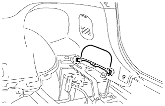
REMOVE NO. 2 INSTRUMENT PANEL UNDER COVER SUB-ASSEMBLY
-
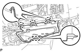
Disengage the 3 claws and guide.
-
Disconnect each connector and remove the No. 2 instrument panel under cover sub-assembly.
-
-
REMOVE GLOVE COMPARTMENT DOOR ASSEMBLY
-
for LHD:
-
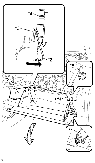
Text in Illustration *1 Glove Compartment Door Stopper Sub-assembly *2 Moulding Remover *3 Lower Instrument Panel Sub-assembly *4 Glove Compartment Door Assembly *5 Stopper Disengage the claw and release the glove compartment door stopper sub-assembly.
-
Insert the moulding remover into the location shown in the illustration.
-
Move the moulding remover in the direction indicated by the arrow to bend the lower instrument panel sub-assembly and release the stopper (A).
Tech Tips
Use the same procedure to release the stopper (B).
-
-
for RHD:
-
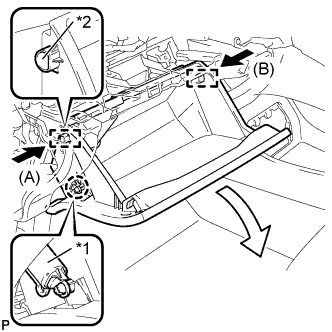
Text in Illustration *1 Glove Compartment Door Stopper Sub-assembly *2 Stopper Disengage the claw and release the glove compartment door stopper sub-assembly.
-
Slightly bend stoppers (A) and (B) in the directions indicated by the arrows in the illustration and pull the glove compartment door assembly until the stoppers are released.
-
-
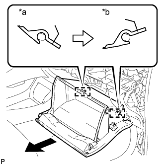
Text in Illustration *a Close *b Open Approximately Open the glove compartment door assembly to approximately 55° from its closed position. Pull it horizontally in the direction indicated by the arrow to disengage the 2 hinges and remove the glove compartment door assembly.
Note
Pulling the glove compartment door assembly upward to remove it causes the hinges to deform. Be sure to pull out the glove compartment door assembly horizontally.
-
-
REMOVE ECU INTEGRATION BOX (for LHD)
-
Disconnect each connector.
-
Disengage the 3 clamps and disconnect the wire harness.
-
Remove the bolt, 2 nuts and ECU integration box.
-
-
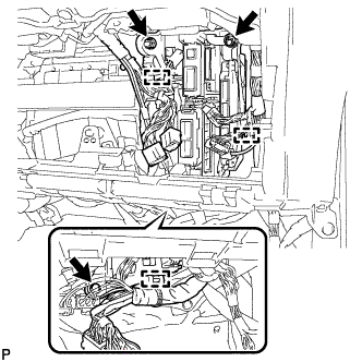
REMOVE ECU INTEGRATION BOX (for RHD)
-
Disconnect each connector.
-
Disengage the clamp and disconnect the wire harness.
-
Remove the bolt, nut and ECU integration box.
-
-
REMOVE POWER MANAGEMENT CONTROL ECU (for LHD)
-
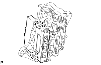
Disengage the 2 claws and remove the power management control ECU.
-
-
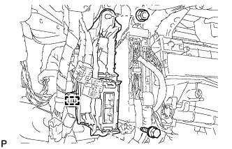
REMOVE POWER MANAGEMENT CONTROL ECU (for RHD)
-
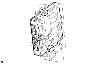
Disengage the 2 claws and remove the power management control ECU.
-