PARKING ASSIST PRE SUPPORT SWITCH REMOVAL
-
PRECAUTION
Note
After turning the power switch off, waiting time may be required before disconnecting the cable from the auxiliary battery negative (-) terminal. Therefore, make sure to read the disconnecting the cable from the auxiliary battery negative (-) terminal notices before proceeding with work Click here.
-
REMOVE REAR NO. 3 FLOOR BOARD
-
Remove the rear No. 3 floor board.
-
-
REMOVE DECK FLOOR BOX RH
-
Fold back the rear No. 2 floor board.
-
Remove the deck floor box RH Click here.
-
-
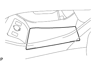
REMOVE REAR NO. 3 FLOOR BOARD UPPER PLATE
-
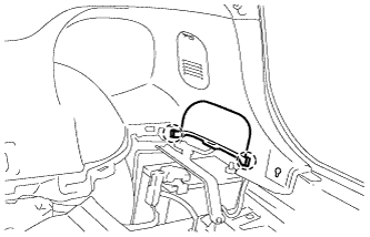
Disengage the 2 claws and remove the rear No. 3 floor board upper plate.
-
-
DISCONNECT CABLE FROM NEGATIVE AUXILIARY BATTERY TERMINAL
Note
When disconnecting the cable, some systems need to be initialized after the cable is reconnected Click here.
-
REMOVE INTEGRATION CONTROL AND PANEL ASSEMBLY
-
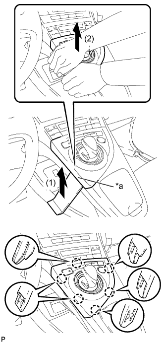
Text in Illustration *a Lift slightly Using a moulding remover, slightly lift the panel at the position shown in the illustration.
-
Pull the integration control and panel assembly in the direction indicated by the arrow to disengage the 6 claws.
-
Disconnect each connector and remove the integration control and panel assembly.
-
-
REMOVE LOWER CENTER INSTRUMENT CLUSTER FINISH PANEL SUB-ASSEMBLY
-
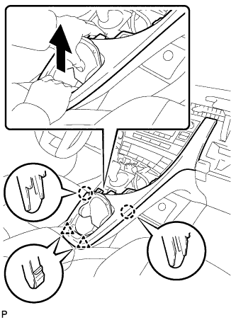
Pull the lower center instrument cluster finish panel sub-assembly in the direction indicated by the arrow to disengage the 2 claws and 2 clips.
-
Pull the lower center instrument cluster finish panel sub-assembly in the direction indicated by the arrow to disengage the 5 claws and remove the lower center instrument cluster finish panel sub-assembly.
-
-
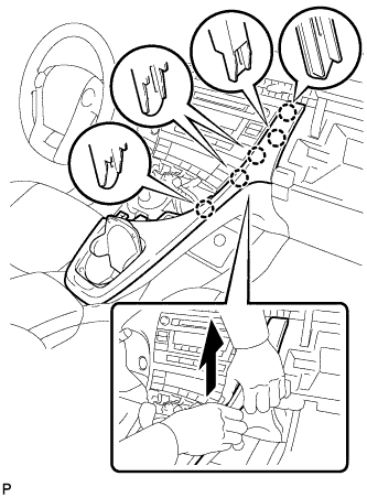
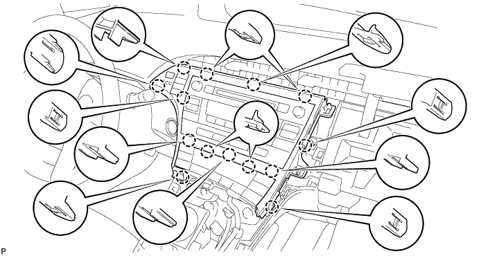
REMOVE INSTRUMENT CLUSTER FINISH PANEL GARNISH
-
Disengage the 14 claws.
-
Disconnect the connector and remove the instrument cluster finish panel garnish.
-
-
REMOVE UPPER INSTRUMENT PANEL FINISH PANEL SUB-ASSEMBLY
-
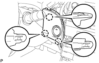
Disengage the 3 claws.
-
Disconnect the connector and remove the upper instrument panel finish panel sub-assembly.
-
-
REMOVE NAVIGATION RECEIVER WITH BRACKET
-
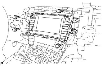
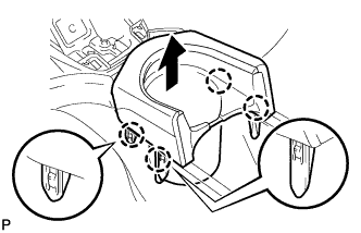
Remove the 4 bolts.
-
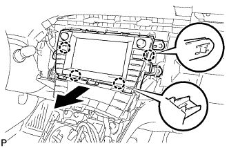
Disengage the 4 claws and remove the navigation receiver with bracket as shown in the illustration.
-
Disconnect each connector.
-
-
REMOVE REAR CONSOLE BOX CUP HOLDER
-
Disengage the 4 claws and remove the rear console box cup holder as shown in the illustration.
-
-
REMOVE CONSOLE BOX CARPET
-
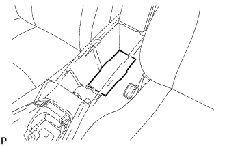
Remove the console box carpet.
-
-
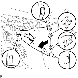
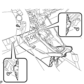
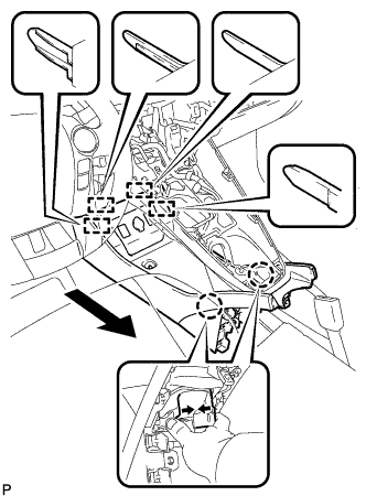
REMOVE REAR CONSOLE BOX ASSEMBLY
-
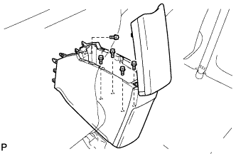
Remove the 5 bolts.
-
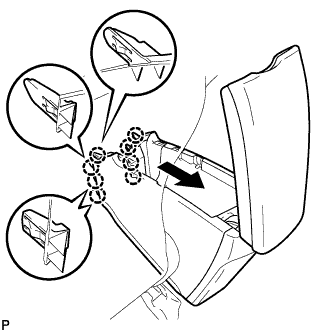
Pull the rear console box assembly in the direction indicated by the arrow to disengage the 8 claws.
-
Disconnect each connector and remove the rear console box assembly.
-
-
REMOVE NO. 1 INDOOR ELECTRICAL KEY ANTENNA ASSEMBLY
-
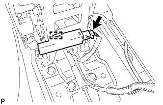
Disconnect the connector.
-
Disengage the clamp and remove the No. 1 indoor electrical key antenna assembly.
Note
Be careful when removing the No. 1 indoor electrical key antenna assembly. If the No. 1 indoor electrical key antenna assembly is dropped, replace it with a new one.
-
-
REMOVE NO. 2 CONSOLE BOX MOUNTING BRACKET
-
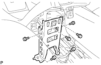
Remove the 6 bolts <B> and No. 2 console box mounting bracket.
-
-
REMOVE CONSOLE BOX INSERT
-
Pull the console box insert in the direction indicated by the arrow to disengage the 4 claws and guide, and remove the console box insert.
-
-
REMOVE FRONT NO. 2 CONSOLE BOX INSERT
-
Pull the front No. 2 console box insert in the direction indicated by the arrow to disengage the 4 claws and guide, and remove the front No. 2 console box insert.
-
-
REMOVE BOX BOTTOM MAT
-
Remove the box bottom mat.
-
-
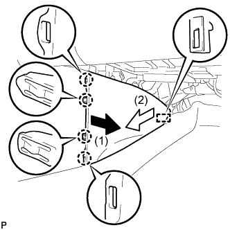
SEPARATE CONSOLE BOX ASSEMBLY
-
Remove the bolt <B> and 2 clips.
-
While pushing the parts shown in the illustration inward, pull the console box assembly in the direction indicated by the arrow to disengage the 2 claws and 4 guides.
-
Disconnect the connector and separate the console box assembly.
-
-
REMOVE AIR CONDITIONING CONTROL ASSEMBLY
-
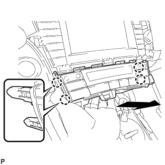
Disengage the 4 claws and remove the air conditioning control assembly as shown in the illustration.
-
Disconnect the connector.
-
-
REMOVE SHIFT LOCK CONTROL UNIT ASSEMBLY
-
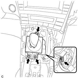
Disconnect the connector from the shift lock control unit assembly.
-
Remove the 3 nuts and shift lock control unit assembly.
-
-
REMOVE UPPER INSTRUMENT PANEL FINISH PANEL ASSEMBLY
-
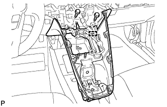
Disengage the clamp.
-
Remove the 2 bolts <A>.
-
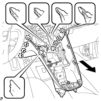
Pull the upper instrument panel finish panel assembly in the direction indicated by the arrow to disengage the 9 claws and remove the upper instrument panel finish panel assembly.
-
-
REMOVE CONSOLE BOX ASSEMBLY
-
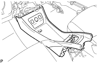
Remove the console box assembly.
-
-
REMOVE NO. 1 SWITCH HOLE BASE
-
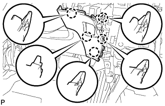
Disengage the 5 claws.
-
Disconnect the connector to remove the No. 1 switch hole base.
-
-
REMOVE PARKING ASSIST PRE SUPPORT SWITCH
-
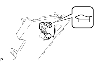
Disengage the 2 claws and remove the parking assist pre support switch.
-