OIL PUMP INSTALLATION

-
INSTALL OIL PUMP ASSEMBLY
-
Install the oil pump assembly with the 3 bolts.
- Torque:
- 21 N*m { 214 kgf*cm, 16 ft.*lbf }
-
-
INSTALL NO. 2 OIL PAN SUB-ASSEMBLY
-
Remove any old packing material and be careful not to drop any oil on the contact surfaces of the cylinder block and oil pan.
-
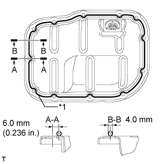
Text in Illustration *1 Seal Packing Apply a continuous bead of seal packing (diameter 4.0 mm (0.157 in.)) as shown in the illustration.
Seal packing Toyota Genuine Seal Packing Black, Three Bond 1207B or equivalent Note
-
Remove any oil from the contact surfaces.
-
Install the oil pan within 3 minutes of applying seal packing.
-
Do not start the engine for at least 2 hours after installing the oil pan.
-
-
Install the No. 2 oil pan sub-assembly with the 10 bolts and 2 nuts.
- Torque:
- 10 N*m { 102 kgf*cm, 7 ft.*lbf }
-
-
INSTALL OIL PAN DRAIN PLUG
-
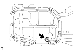
Install a new gasket and the oil pan drain plug.
- Torque:
- 37 N*m { 377 kgf*cm, 27 ft.*lbf }
-
-
INSTALL CRANKSHAFT TIMING GEAR KEY
-
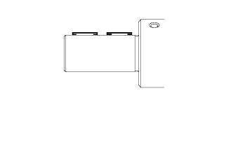
Using a plastic-faced hammer, tap in the 2 crankshaft timing gear keys.
Tech Tips
Tap in the crankshaft timing gear keys until they contact the crankshaft as shown in the illustration.
-
-
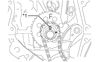
INSTALL NO. 1 CRANKSHAFT POSITION SENSOR PLATE
-
Install the No. 1 crankshaft position sensor plate with the "F" mark facing forward.
-
-
INSTALL NO. 2 CHAIN SUB-ASSEMBLY
-
Temporarily install the crankshaft pulley bolt.
-
Turn the crankshaft counterclockwise to position the timing gear key at the 9 o'clock position.
-
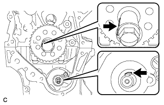
Turn the drive shaft so that the cutout faces the 12 o'clock position.
-
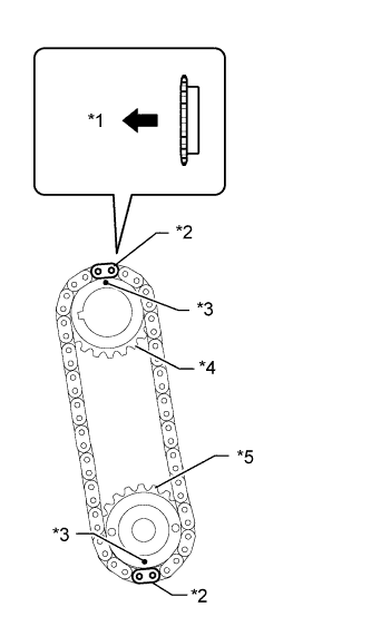
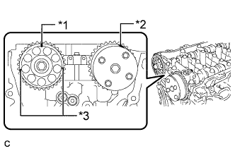
Text in Illustration *1 Front *2 Mark Plate (Yellow) *3 Timing Mark *4 Oil Pump Drive Gear *5 Oil Pump Drive Shaft Gear Align the yellow mark links with the timing marks of each gear as shown in the illustration.
Tech Tips
Be sure to position the mark plates at the front of the engine.
-
Install the sprockets onto the crankshaft and oil pump shaft with the chain on the gears.
-
Temporarily tighten the oil pump drive shaft gear with the nut.
-
Insert the damper spring into the adjusting hole, and then install the chain tensioner plate with the bolt.
- Torque:
- 10 N*m { 102 kgf*cm, 7 ft.*lbf }
-
Temporarily tighten the crankshaft pulley with the bolt.
-
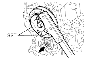
Using SST, install the oil pump drive shaft gear nut while holding the crankshaft pulley.
- SST
- 09213-58014 ( 91551-80840 )
- 09330-00021
- Torque:
- 28 N*m { 286 kgf*cm, 21 ft.*lbf }
-
Remove the crankshaft pulley and crankshaft pulley bolt.
-
-
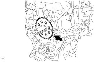
INSTALL CRANKSHAFT TIMING SPROCKET
-
Install the crankshaft timing sprocket.
-
-
INSTALL NO. 1 CHAIN VIBRATION DAMPER
-
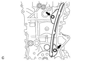
Install the No. 1 chain vibration damper with the 2 bolts.
- Torque:
- 21 N*m { 214 kgf*cm, 15 ft.*lbf }
-
-
SET NO. 1 CYLINDER TO TDC / COMPRESSION
-
Text in Illustration *1 Timing Gear Key Temporarily install the crankshaft pulley bolt.
-
Turn the crankshaft to position the timing gear key to the top.
-
Text in Illustration *1 Timing Mark (Rectangle) *2 Timing Mark *3 Mark (Circle) Check that the timing marks on the camshaft timing gear assembly and camshaft timing sprocket are aligned as shown in the illustration.
Tech Tips
There are 3 marks on the camshaft timing sprocket. Make sure that the timing mark (rectangle) is at the top.
-
Align the mark plate (orange) with the timing mark as shown in the illustration and install the chain sub-assembly.
-
Remove the crankshaft pulley bolt.
-
-
INSTALL CHAIN SUB-ASSEMBLY