HV RELAY ASSEMBLY INSTALLATION
-
INSTALL ELECTRIC VEHICLE FUSE
Tech Tips
Perform this procedure only when replacement of the electric vehicle fuse is necessary.
-
Install the electric vehicle fuse with the 2 bolts.
- Torque:
- 2.1 N*m { 21 kgf*cm, 19 in.*lbf }
-
Connect the clamp to the hybrid battery junction block assembly.
-
-
INSTALL NO. 4 HYBRID VEHICLE BATTERY PACK WIRE
Tech Tips
Perform this procedure only when replacement of the No. 4 hybrid battery pack wire is necessary.
-
Install the No. 4 hybrid vehicle battery pack wire with the 3 clamps and 2 connectors to the hybrid battery junction block assembly.
-
-
INSTALL HYBRID BATTERY JUNCTION BLOCK ASSEMBLY
CAUTION:
Be sure to wear insulated gloves and protective goggles.
-
Install the hybrid battery junction block assembly with the 3 nuts.
- Torque:
- 8.4 N*m { 86 kgf*cm, 74 in.*lbf }
-
Connect the 2 connectors to the hybrid battery junction block.
Note
Make sure that the connectors are connected securely.
-
Connect the 3 connectors to the hybrid battery junction block.
Note
Make sure that the connectors are connected securely.
-
Connect the 10 clamps.
-
-
CONNECT FRAME WIRE
CAUTION:
Wear insulated gloves.
-
Connect the shield wire ground.
-
Using an insulated tool, connect the frame wire with the 2 nuts.
- Torque:
- 9.0 N*m { 92 kgf*cm, 80 in.*lbf }
-
-
CONNECT EV CHARGER WIRE
CAUTION:
Wear insulated gloves.
-
Connect the shield wire ground with the nut.
- Torque:
- 8.0 N*m { 82 kgf*cm, 71 in.*lbf }
-
Connect the connector.
Note
Make sure that the connector is connected securely.
-
-
INSTALL UPPER HYBRID BATTERY COVER SUB-ASSEMBLY
CAUTION:
Be sure to wear insulated gloves and protective goggles.
-
Install the upper hybrid battery cover sub-assembly with the 2 bolts and 4 nuts.
- Torque:
- Bolt
- 22 N*m { 224 kgf*cm, 16 ft.*lbf }
- Nut
- 22 N*m { 221 kgf*cm, 16 ft.*lbf }
-
-
INSTALL NO. 1 HYBRID VEHICLE BATTERY COVER PANEL LH
CAUTION:
Wear insulated gloves.
-
Install the No. 1 hybrid vehicle battery cover panel LH with the 6 bolts.
- Torque:
- 10 N*m { 102 kgf*cm, 7 ft.*lbf }
-
-
INSTALL NO. 1 HYBRID VEHICLE BATTERY COVER PANEL RH
CAUTION:
Wear insulated gloves.
-
Install the No. 1 hybrid vehicle battery cover panel RH with the 6 bolts.
- Torque:
- 10 N*m { 102 kgf*cm, 7 ft.*lbf }
-
Connect the 4 clamps.
-
-
INSTALL NO. 1 HYBRID VEHICLE BATTERY SHIELD PANEL
CAUTION:
Wear insulated gloves.
-
Install the No. 1 hybrid vehicle battery shield panel with the 7 nuts.
- Torque:
- 10 N*m { 103 kgf*cm, 7 ft.*lbf }
-
Connect the connector and clamp.
-
Install the electrical key oscillator with the 2 claws and 3 clamp.
-
-
INSTALL NO. 2 HYBRID VEHICLE BATTERY SHIELD PANEL
CAUTION:
Wear insulated gloves.
-
Install the No. 2 hybrid vehicle battery shield panel with the 3 nuts.
- Torque:
- 7.5 N*m { 76 kgf*cm, 66 in.*lbf }
-
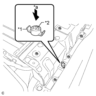
Text in Illustration *1 Battery Cover Lock Striker *2 Button *a Push Install the battery cover lock striker, then push the button to lock it.
-
-
INSTALL REAR NO. 1 HYBRID BATTERY SHIELD
CAUTION:
Wear insulated gloves.
-
Install the rear No. 1 hybrid battery shield with the 9 bolts.
- Torque:
- 10 N*m { 102 kgf*cm, 7 ft.*lbf }
-
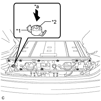
Text in Illustration *1 Battery Cover Lock Striker *2 Button *a Push Install the battery cover lock striker, then push the button to lock it.
-
Connect the clamp.
-
Connect the 2 clamps and connector.
-
-
INSTALL NO. 4 HYBRID VEHICLE BATTERY CARRIER BRACKET
-
Install the No. 4 hybrid vehicle battery carrier bracket with the bolt.
- Torque:
- 7.5 N*m { 76 kgf*cm, 66 in.*lbf }
-
-
INSTALL NO. 3 HYBRID BATTERY EXHAUST DUCT
-
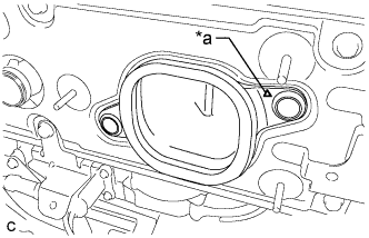
Text in Illustration *a Positioning Mark Install the No. 3 hybrid battery exhaust duct (for RH side) with the 2 clips.
Tech Tips
Install the No. 3 hybrid battery exhaust duct so that the positioning mark is on the right side of the vehicle.
-
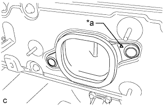
Text in Illustration *a Positioning Mark Install the No. 3 hybrid battery exhaust duct (for LH side) with the 2 clips.
Tech Tips
Install the No. 3 hybrid battery exhaust duct so that the positioning mark is on the right side of the vehicle.
-
-
INSTALL HYBRID BATTERY HOSE ASSEMBLY
-
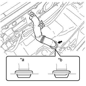
Text in Illustration *a Correct *b Incorrect Install the hybrid battery hose assembly with the claw and grommet.
Note
Make sure that there is no space or a gap between the grommet and the body.
-
Connect the clip.
-
-
INSTALL BATTERY COOLING BLOWER ASSEMBLY (for LH Side)
Note
-
Be sure not to touch the fan part of the battery cooling blower assembly.
-
Do not lift the battery cooling blower assembly using the wire harness.
-
When replacing the battery cooling blower assembly (for LH side) with a new one:
-
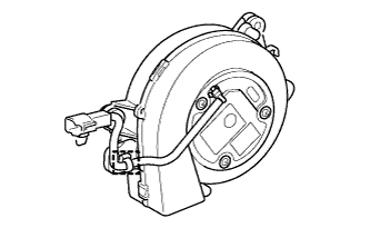
Connect the clamp to the battery cooling blower assembly (for LH side).
-
-
Install the battery cooling blower assembly with the 3 nuts.
- Torque:
- 7.5 N*m { 76 kgf*cm, 66 in.*lbf }
-
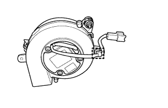
Connect the connector and clamp.
-
-
INSTALL BATTERY COOLING BLOWER ASSEMBLY (for RH Side)
Note
-
Be sure not to touch the fan part of the battery cooling blower assembly.
-
Do not lift the battery cooling blower assembly using the wire harness.
-
When replacing the battery cooling blower assembly (for RH side) with a new one:
-
Connect the clamp to the battery cooling blower assembly (for RH side).
-
-
Install the battery cooling blower assembly with the 3 nuts.
- Torque:
- 7.5 N*m { 76 kgf*cm, 66 in.*lbf }
-
Connect the connector and clamp.
-
-
INSTALL DECK TRIM SIDE PANEL ASSEMBLY RH
-
Engage the 7 claws and 2 clips.
-
Install the deck trim side panel assembly RH with the screw.
-
-
INSTALL TONNEAU COVER HOLDER CAP (for RH Side)
Tech Tips
Use the same procedure described for the LH side Click here.
-
INSTALL LUGGAGE HOLD BELT STRIKER ASSEMBLY (for RH Side)
Tech Tips
Use the same procedure described for the LH side Click here.
-
INSTALL REAR SIDE SEAT BACK ASSEMBLY RH
-
Engage the 2 guides as shown in the illustration.
-
Engage the 3 fasteners.
-
Install the rear side seatback assembly RH with the bolt.
- Torque:
- 18 N*m { 184 kgf*cm, 13 ft.*lbf }
-
-
INSTALL REAR SEAT CUSHION ASSEMBLY
-
Place the rear seat cushion assembly in the cabin.
Note
Be careful not to damage the vehicle body.
-
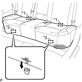
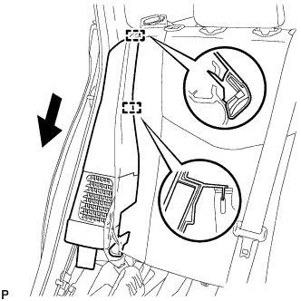
Text in Illustration *1 Rear Hook *2 Front Hook Engage the 2 rear hooks of the rear seat cushion assembly to the rear seatback assembly.
-
Engage the 2 front hooks of the rear seat cushion assembly to the vehicle body as shown in the illustration.
-
Confirm that the rear seat cushion assembly is firmly installed.
Note
When installing the rear seat cushion assembly, make sure that the seat belt buckles are not under the rear seat cushion assembly.
-
-
INSTALL REAR DOOR OPENING TRIM WEATHERSTRIP RH
-
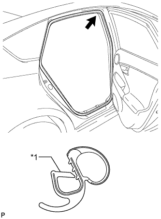
Text in Illustration *1 Alignment Mark (Blue) Align the alignment mark (Blue) on the weatherstrip with the protruding portion on the body indicated by the arrow in the illustration, and install the rear door opening trim weatherstrip RH.
Note
After installation, check that the corners fit correctly.
-
-
INSTALL REAR DOOR SCUFF PLATE RH
Tech Tips
Use the same procedure described for the LH side Click here.
-
INSTALL REAR DECK TRIM COVER
-
Engage the 4 claws to install the rear deck trim cover.
-
-
INSTALL DECK TRIM SERVICE HOLE COVER
-
Engage the 4 guides.
-
Engage the 4 claws to install the deck trim service hole cover.
-
-
INSTALL REAR NO. 1 FLOOR BOARD
-
Engage the 3 fasteners.
-
Install the rear No. 1 floor board with the clip.
-
Engage each fastener.
-
-
INSTALL REAR NO. 1 FLOOR BOARD SUB-ASSEMBLY
-
Engage the claw and 3 clips to install the rear No. 1 floor board sub-assembly.
-
-
INSTALL REAR NO. 2 FLOOR BOARD SUB-ASSEMBLY
-
Engage the claw and 2 clips to install the rear No. 2 floor board sub-assembly.
-
-
INSTALL TONNEAU COVER ASSEMBLY
-
Install the tonneau cover assembly.
-
-
INSTALL DECK FLOOR BOX LH
Tech Tips
Use the same procedure described for the RH side Click here.
-
INSTALL REAR NO. 4 FLOOR BOARD SUB-ASSEMBLY
-
Install the rear No. 4 floor board sub-assembly.
-
-
INSTALL REAR NO. 2 FLOOR BOARD
-
Engage the 3 fasteners.
-
Install the rear No. 2 floor board with the 2 clips.
-
-
INSTALL SERVICE PLUG GRIP
-
CURRENT SENSOR OFFSET LEARNING
Tech Tips
Perform this procedure when the hybrid battery junction block assembly or power management control ECU has been replaced.
-
Connect the GTS to the DLC3.
-
Turn the power switch on (READY).
-
Perform a road test.
Note
Accelerate/decelerate gently. Avoid rapid acceleration/deceleration.
-
Enter the following menus: Powertrain / Hybrid Control / Data List / Power Resource IB.
-
Drive the vehicle with the value of Data List item "Power Resource IB" between -50 A and 50 A.
Tech Tips
Distance and driving time are not specified.
-
-
Turn the power switch off and leave the vehicle for 30 seconds or more.
-
Turn the power switch on (IG).
-
Enter the following menus: Powertrain / Hybrid Control / Data List / Power Resource IB.
-
Check that the value of "Power Resource IB" is between - 0.5 A and 0.5 A with the power switch on (IG).
Note
If the value is outside the specified range, perform the road test again.
Tech Tips
-
If the power switch is on (IG) and value of "Power Resource IB" is between - 0.5 A and 0.5 A, current sensor offset learning has been completed.
-
Even if the current sensor offset learning is not complete, the current sensor value will be corrected by repeating the road test a maximum of 7 times.
-
-