HV RELAY ASSEMBLY REMOVAL
-
PRECAUTION
-
REMOVE SERVICE PLUG GRIP
-
REMOVE INVERTER COVER
CAUTION:
Wear insulated gloves.
-
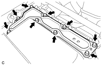
Remove the 9 bolts and inverter cover.
Note
Make sure to pull the inverter cover straight up, as a connector is connected to the bottom of the cover.
-
-
CHECK TERMINAL VOLTAGE
CAUTION:
Wear insulated gloves.
Note
Do not allow any foreign matter or water to enter the inverter with converter assembly.
-
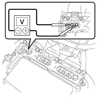
Using a voltmeter, measure the voltage between the terminals of the 2 phase connectors.
Standard voltage 0 V Tech Tips
Use measuring range of DC 750 V or more on the voltmeter.
-
-
INSTALL INVERTER COVER
CAUTION:
Wear insulated gloves.
-
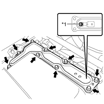
Text in Illustration *1 Interlock Install the inverter cover with the 9 bolts to the inverter with converter assembly.
- Torque:
- 11 N*m { 112 kgf*cm, 8 ft.*lbf }
Note
-
Make sure that the interlock is fully engaged.
-
Do not allow any foreign matter or water to enter the inverter with converter assembly.
-
-
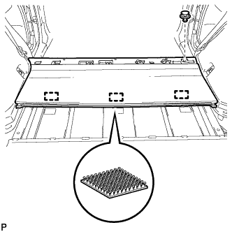
REMOVE REAR NO. 2 FLOOR BOARD
-
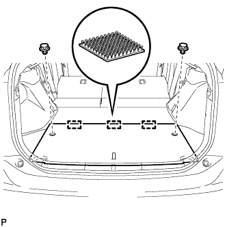
Using a clip remover, remove the 2 clips.
-
Disengage the 3 fasteners and remove the rear No. 2 floor board.
-
-
REMOVE REAR NO. 4 FLOOR BOARD SUB-ASSEMBLY
-
Remove the rear No.4 floor board sub-assembly.
-
-
REMOVE DECK FLOOR BOX LH
Tech Tips
Use the same procedure described for the RH side Click here.
-
REMOVE TONNEAU COVER ASSEMBLY
-
Remove the tonneau cover assembly.
-
-
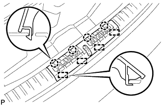
REMOVE REAR NO. 2 FLOOR BOARD SUB-ASSEMBLY
-
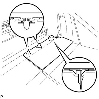
Disengage the claw and 2 clips, and remove the rear No. 2 floor board sub-assembly.
-
-
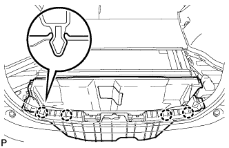
REMOVE REAR NO. 1 FLOOR BOARD SUB-ASSEMBLY
-
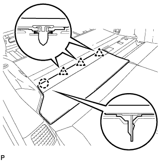
Disengage the claw and 3 clips, and remove the rear No. 1 floor board sub-assembly.
-
-
REMOVE REAR NO. 1 FLOOR BOARD
-
Fold the rear seatback assembly LH forward.
-
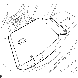
Text in Illustration *1 Fastener Disengage the fastener.
-
Fold the rear seatback assembly LH forward.
-
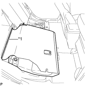
Text in Illustration *1 Fastener Disengage the fastener.
-
Using a clip remover, remove the clip.
-
Disengage the 3 fasteners and remove the rear No. 1 floor board.
-
-
REMOVE DECK TRIM SERVICE HOLE COVER
-
Disengage the 4 claws.
-
Disengage the 4 guides and remove the deck trim service hole cover.
-
-
REMOVE REAR DECK TRIM COVER
-
Disengage the 4 claws and remove the rear deck trim cover.
-
-
REMOVE REAR DOOR SCUFF PLATE RH
Tech Tips
Use the same procedure described for the LH side Click here.
-
REMOVE REAR DOOR OPENING TRIM WEATHERSTRIP RH
Tech Tips
Use the same procedure described for the LH side Click here.
-
REMOVE REAR SEAT CUSHION ASSEMBLY
-
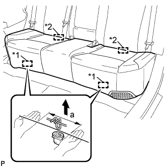
Text in Illustration *1 Front Hook *2 Rear Hook Disengage the front hook of the rear seat cushion assembly from the vehicle body as shown in the illustration.
Standard Measurement Dimension Measurement a 100 mm (3.94 in.) or less Note
Follow the instructions below carefully as the cushion frame can be deformed easily.
-
Choose a front hook to disengage first. Place your hands near the front hook as shown in the illustration. Then lift the seat cushion to disengage the front hook.
-
Repeat the above procedure for the other hook.
-
-
Disengage the 2 rear hooks of the rear seat cushion assembly from the rear seatback assembly.
-
Remove the rear seat cushion assembly.
Note
Be careful not to damage the vehicle body.
-
-
REMOVE REAR SIDE SEAT BACK ASSEMBLY RH
-
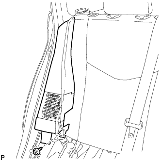
Remove the bolt.
-
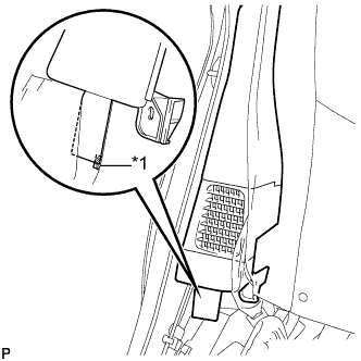
Text in Illustration *1 Fastener Disengage the fastener.
-
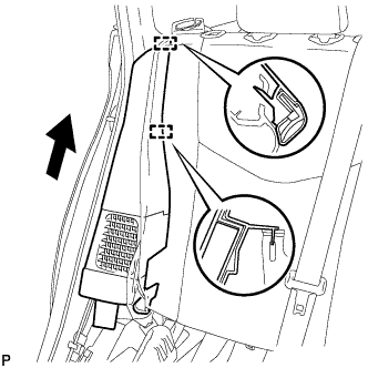
Disengage the 2 guides and remove the rear side seatback assembly RH as shown in the illustration.
-
-
REMOVE LUGGAGE HOLD BELT STRIKER ASSEMBLY (for RH Side)
Tech Tips
Use the same procedure described for the LH side Click here.
-
REMOVE TONNEAU COVER HOLDER CAP (for RH Side)
Tech Tips
Use the same procedure described for the LH side Click here.
-
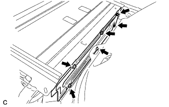
REMOVE DECK TRIM SIDE PANEL ASSEMBLY RH
-
Remove the screw.
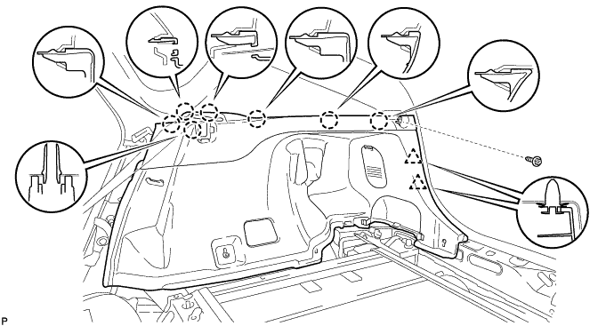
-
Disengage the 7 claws and 2 clips, and remove the deck trim side panel assembly RH.
-
-
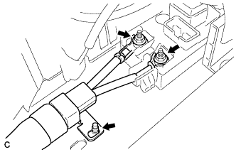
REMOVE BATTERY COOLING BLOWER ASSEMBLY (for RH Side)
Note
-
Be sure not to touch the fan part of the battery cooling blower assembly.
-
Do not lift the battery cooling blower assembly using the wire harness.
-
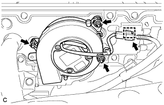
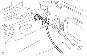
Disconnect the connector and clamp from the battery cooling blower assembly.
-
Remove the 3 nuts and battery cooling blower assembly (for RH side).
-
-
REMOVE BATTERY COOLING BLOWER ASSEMBLY (for LH Side)
Note
-
Be sure not to touch the fan part of the battery cooling blower assembly.
-
Do not lift the battery cooling blower assembly using the wire harness.
-
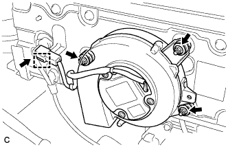
Disconnect the connector and clamp from the battery cooling blower assembly.
-
Remove the 3 nuts and battery cooling blower assembly (for LH side).
-
-
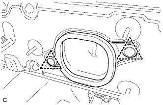
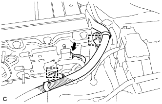
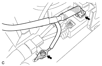
REMOVE HYBRID BATTERY HOSE ASSEMBLY
-
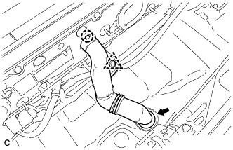
Disconnect the clip.
-
Disengage the claw.
-
Disconnect the grommet and remove the hybrid battery hose assembly.
-
-
REMOVE NO. 3 HYBRID BATTERY EXHAUST DUCT
-
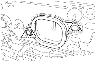
Remove the 2 clips and No. 3 hybrid battery exhaust duct (for RH side).
-
Remove the 2 clips and No. 3 hybrid battery exhaust duct (for LH side).
-
-
REMOVE NO. 4 HYBRID VEHICLE BATTERY CARRIER BRACKET
-
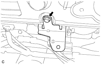
Remove the bolt and No. 4 hybrid vehicle battery carrier bracket.
-
-
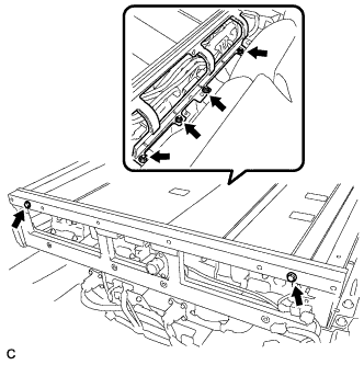
REMOVE REAR NO. 1 HYBRID BATTERY SHIELD
CAUTION:
Wear insulated gloves.
-
Disconnect the connector and 2 clamps.
-
Disconnect the clamp.
-
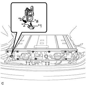
Text in Illustration *1 Battery Cover Lock Striker *2 Button *a Projection *b Turn Using the service plug grip, remove the battery cover lock striker.
Tech Tips
Insert the projection part of the service plug grip, and turn the button of the battery cover lock striker counterclockwise, and release the lock.
-
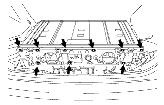
Remove the 9 bolts and rear No. 1 hybrid battery shield.
-
-
REMOVE NO. 2 HYBRID VEHICLE BATTERY SHIELD PANEL
CAUTION:
Wear insulated gloves.
-
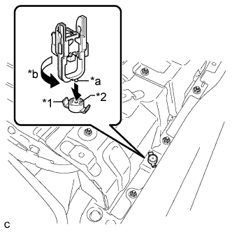
Text in Illustration *1 Battery Cover Lock Striker *2 Button *a Projection *b Turn Using the service plug grip, remove the battery cover lock striker.
Tech Tips
Insert the projection part of the service plug grip, and turn the button of the battery cover lock striker counterclockwise, and release the lock.
-
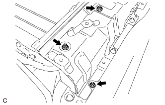
Remove the 3 nuts and No. 2 hybrid vehicle battery shield panel.
-
-
REMOVE NO. 1 HYBRID VEHICLE BATTERY SHIELD PANEL
CAUTION:
Wear insulated gloves.
-
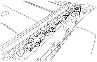
Disengage the 2 claws and remove the 3 clamps and electrical key oscillator.
-
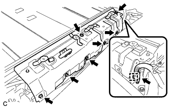
Disconnect the connector and clamp.
-
Remove the 7 nuts and No. 1 hybrid vehicle battery shield panel.
-
-
REMOVE NO. 1 HYBRID VEHICLE BATTERY COVER PANEL RH
CAUTION:
Wear insulated gloves.
-
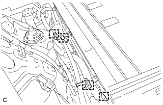
Disconnect the 4 clamps.
-
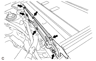
Remove the 6 bolts and No. 1 hybrid vehicle battery cover panel RH.
-
-
REMOVE NO. 1 HYBRID VEHICLE BATTERY COVER PANEL LH
CAUTION:
Wear insulated gloves.
-
Remove the 6 bolts and No. 1 hybrid vehicle battery cover panel LH.
-
-
REMOVE UPPER HYBRID BATTERY COVER SUB-ASSEMBLY
CAUTION:
Wear insulated gloves.
-
Remove the 2 bolts, 4 nuts and upper hybrid battery cover sub-assembly.
-
-
DISCONNECT EV CHARGER WIRE
CAUTION:
Wear insulated gloves.
-
Disconnect the connector.
Note
Insulate the disconnected connector with insulating tape.
-
Remove the nut and disconnect the electric vehicle charger wire.
-
-
DISCONNECT FRAME WIRE
CAUTION:
Wear insulated gloves.
-
Using an insulated tool, remove the 2 nuts.
-
Disconnect the shield wire ground and frame wire.
Note
Insulate the disconnected terminal with insulating tape.
-
-
REMOVE HYBRID BATTERY JUNCTION BLOCK ASSEMBLY
CAUTION:
Be sure to wear insulated gloves and protective goggles.
-
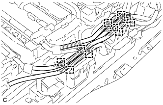
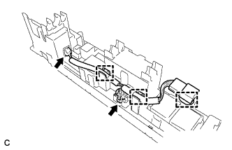
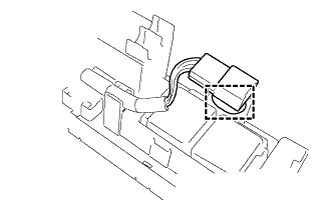
Disconnect the 10 clamps.
-
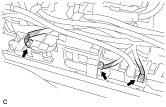
Disconnect the 3 connectors from the hybrid battery junction block assembly.
-
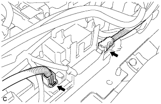
Disconnect the 2 connectors from the hybrid battery junction block assembly.
Note
Insulate the disconnected connectors with insulating tape.
-
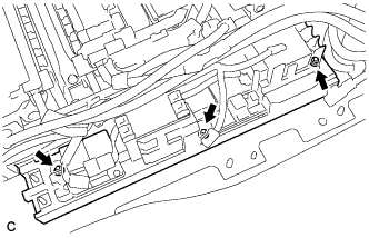
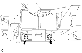
Remove the 3 nuts and hybrid battery junction block assembly.
-
-
REMOVE NO. 4 HYBRID VEHICLE BATTERY PACK WIRE
Tech Tips
Perform this procedure only when replacement of the No. 4 hybrid battery pack wire is necessary.
-
Disconnect the 2 connectors and 3 clamps and remove the No. 4 hybrid vehicle battery pack wire.
-
-
REMOVE ELECTRIC VEHICLE FUSE
Tech Tips
Perform this procedure only when replacement of the electric vehicle fuse is necessary.
-
Disconnect the clamp from the hybrid battery junction block assembly.
-
Remove the 2 bolts and electric vehicle fuse.
-