FRAME WIRE INSTALLATION
-
INSTALL FRAME WIRE
CAUTION:
Wear insulated gloves.
Note
Insulate the removed terminals with insulating tape.
-
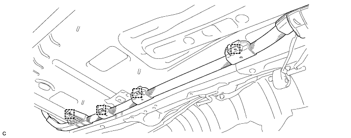
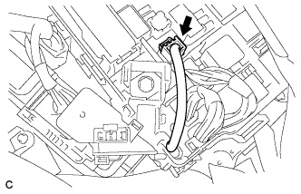
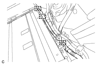
Install the frame wire with the 4 new clamps.
-
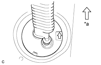
Text in Illustration *a Front Side Insert the frame wire into the floor panel hole.
Tech Tips
The arrow should be pointing toward the front of the vehicle.
-
Install the bolt.
- Torque:
- 8.4 N*m { 85 kgf*cm, 74 in.*lbf }
-
Install the nut and clamp.
- Torque:
- 8.4 N*m { 85 kgf*cm, 74 in.*lbf }
-
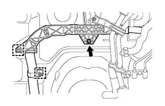
Install the nut and 2 clamps.
- Torque:
- 8.4 N*m { 85 kgf*cm, 74 in.*lbf }
-
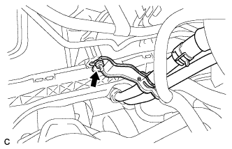
Install the heater water pipe sub-assembly with the nut.
- Torque:
- 9.8 N*m { 100 kgf*cm, 87 in.*lbf }
-
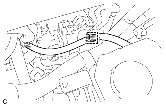
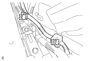
Connect the clamp.
-
Connect the clamp.
-
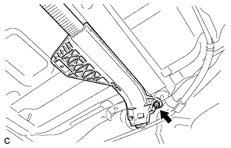
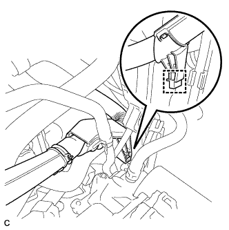
Connect the connector to the engine room junction block assembly.
-
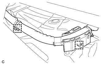
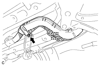
Connect the 2 wire harness clamps to the floor panel.
-
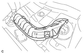
Connect the clamp to the floor panel to install the wire harness protector.
-
Connect the shield wire ground.
-
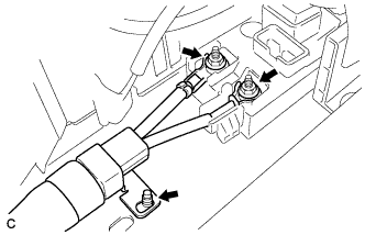
Using an insulated tool, install the frame wire on the hybrid battery junction block assembly with the 2 nuts.
- Torque:
- 9.0 N*m { 92 kgf*cm, 80 in.*lbf }
Note
-
Make sure that the ends of the frame wire are not crossed over each other.
-
Be sure to connect the ends of the frame wire to the connect terminals.
-
Connect the 3 clamps.
-
Connect the 2 clamps.
-
-
CONNECT EV CHARGER WIRE
CAUTION:
Wear insulated gloves.
-
Connect the shield wire ground with the nut.
- Torque:
- 8.0 N*m { 82 kgf*cm, 71 in.*lbf }
-
Connect the connector.
Note
Make sure that the connector is connected securely.
-
-
CONNECT CABLE TO POSITIVE AUXILIARY BATTERY TERMINAL
-
Connect the cable with the nut.
- Torque:
- 7.6 N*m { 77 kgf*cm, 67 in.*lbf }
-
Install the terminal cover.
-
-
INSTALL NO. 2 HYBRID VEHICLE BATTERY SHIELD PANEL
CAUTION:
Wear insulated gloves.
-
Install the No. 2 hybrid vehicle battery shield panel with the 3 nuts.
- Torque:
- 7.5 N*m { 76 kgf*cm, 66 in.*lbf }
-
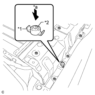
Text in Illustration *1 Battery Cover Lock Striker *2 Button *a Push Install the battery cover lock striker, then push the button to lock it.
-
-
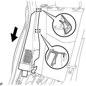
INSTALL DECK TRIM SIDE PANEL ASSEMBLY RH
-
Engage the 7 claws and 2 clips.
-
Install the deck trim side panel assembly RH with the screw.
-
-
INSTALL TONNEAU COVER HOLDER CAP (for RH Side)
Tech Tips
Use the same procedure described for the LH side Click here.
-
INSTALL LUGGAGE HOLD BELT STRIKER ASSEMBLY (for RH Side)
Tech Tips
Use the same procedure described for the LH side Click here.
-
INSTALL REAR SIDE SEAT BACK ASSEMBLY RH
-
Engage the 2 guides as shown in the illustration.
-
Engage the 3 fasteners.
-
Install the rear side seatback assembly RH with the bolt.
- Torque:
- 18 N*m { 184 kgf*cm, 13 ft.*lbf }
-
-
INSTALL REAR SEAT CUSHION ASSEMBLY
-
Place the rear seat cushion assembly in the cabin.
Note
Be careful not to damage the vehicle body.
-
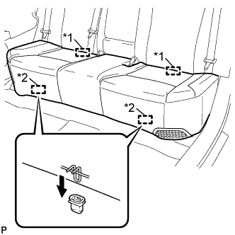
Text in Illustration *1 Rear Hook *2 Front Hook Engage the 2 rear hooks of the rear seat cushion assembly to the rear seatback assembly.
-
Engage the 2 front hooks of the rear seat cushion assembly to the vehicle body as shown in the illustration.
-
Confirm that the rear seat cushion assembly is firmly installed.
Note
When installing the rear seat cushion assembly, make sure that the seat belt buckles are not under the rear seat cushion assembly.
-
-
INSTALL REAR DOOR OPENING TRIM WEATHERSTRIP RH
-
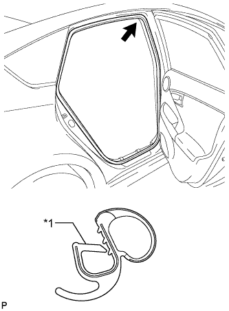
Text in Illustration *1 Alignment Mark (Blue) Align the alignment mark (Blue) on the weatherstrip with the protruding portion on the body indicated by the arrow in the illustration, and install the rear door opening trim weatherstrip RH.
Note
After installation, check that the corners fit correctly.
-
-
INSTALL REAR DOOR SCUFF PLATE RH
Tech Tips
Use the same procedure described for the LH side Click here.
-
INSTALL REAR DECK TRIM COVER
-
Engage the 4 claws to install the rear deck trim cover.
-
-
INSTALL DECK TRIM SERVICE HOLE COVER
-
Engage the 4 guides.
-
Engage the 4 claws to install the deck trim service hole cover.
-
-
INSTALL REAR NO. 1 FLOOR BOARD
-
Engage the 3 fasteners.
-
Install the rear No. 1 floor board with the clip.
-
Engage each fastener.
-
-
INSTALL REAR NO. 1 FLOOR BOARD SUB-ASSEMBLY
-
Engage the claw and 3 clips to install the rear No. 1 floor board sub-assembly.
-
-
INSTALL REAR NO. 2 FLOOR BOARD SUB-ASSEMBLY
-
Engage the claw and 2 clips to install the rear No. 2 floor board sub-assembly.
-
-
INSTALL TONNEAU COVER ASSEMBLY
-
Install the tonneau cover assembly.
-
-
INSTALL DECK FLOOR BOX LH
Tech Tips
Use the same procedure described for the RH side Click here.
-
INSTALL REAR NO. 4 FLOOR BOARD SUB-ASSEMBLY
-
Install the rear No. 4 floor board sub-assembly.
-
-
INSTALL REAR NO. 2 FLOOR BOARD
-
Engage the 3 fasteners.
-
Install the rear No. 2 floor board with the 2 clips.
-
-
INSTALL FRONT SUSPENSION MEMBER BRACE REAR RH
-
Using a transmission jack, hold the front suspension cross member.
Note
Be sure to position the transmission jack to properly support the front suspension cross member.
-
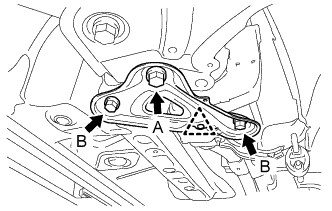
Install the front suspension member brace rear RH with the bolt (A) and the 2 bolts (B).
- Torque:
- Bolt A
- 137 N*m { 1397 kgf*cm, 101 ft.*lbf }
- Bolt B
- 93 N*m { 948 kgf*cm, 69 ft.*lbf }
-
Install the clip.
-
-
INSTALL FRONT FLOOR COVER CENTER RH
-
Install the front center floor cover RH with the 3 clips.
-
-
INSTALL FRONT FLOOR COVER RH
-
Install the front floor cover RH with the 4 clips.
-
Install the bolt.
-
-
INSTALL FRONT NO. 1 FLOOR HEAT INSULATOR
-
Install the No. 1 front floor heat insulator with the 3 nuts.
-
-
INSTALL FRONT EXHAUST PIPE ASSEMBLY
-
INSTALL INVERTER WITH CONVERTER ASSEMBLY