HV BATTERY STACK INSTALLATION
-
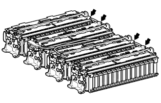
INSTALL NO. 4 HYBRID VEHICLE SUPPLY STACK SUB-ASSEMBLY
CAUTION:
Be sure to wear insulated gloves and protective goggles.
Note
Before installing a new hybrid vehicle supply stack sub-assembly, the voltage should be adjusted to the appropriate value.
-
Install the No. 4 hybrid vehicle supply stack sub-assembly with the 4 nuts.
- Torque:
- 19 N*m { 194 kgf*cm, 14 ft.*lbf }
-
Install the No. 2 hybrid vehicle battery shield reinforcement with the 3 bolts.
- Torque:
- 11 N*m { 112 kgf*cm, 8 ft.*lbf }
Tech Tips
Install the center bolt first.
-
Install the No. 1 hybrid vehicle battery shield reinforcement with the 3 bolts.
- Torque:
- 11 N*m { 112 kgf*cm, 8 ft.*lbf }
Tech Tips
Install the center bolt first.
-
Install the No. 1 hybrid battery exhaust duct and No. 2 hybrid battery exhaust duct with the 8 claws.
-
Install the No. 5 hybrid battery intake duct with the 4 claws.
-
Using an insulated tool, Install the No. 3 hybrid vehicle battery pack cable with a new bolt.
- Torque:
- 5.0 N*m { 51 kgf*cm, 44 in.*lbf }
Note
-
The terminal cover should be connected securely.
-
Make sure to connect the No. 3 hybrid vehicle battery pack cable securely. If the power switch is turned on (READY) without the No. 3 hybrid vehicle battery pack cable connected, the inner circuit of the battery smart unit will be damaged due to high voltage supplied through the battery block voltage detection circuit.
-
Using an insulated tool, connect the No. 2 hybrid vehicle battery pack cable with a new bolt.
- Torque:
- 5.0 N*m { 51 kgf*cm, 44 in.*lbf }
Note
The terminal cover should be connected securely.
-
-
INSTALL NO. 3 HYBRID VEHICLE SUPPLY STACK SUB-ASSEMBLY
CAUTION:
Be sure to wear insulated gloves and protective goggles.
Note
Before installing a new hybrid vehicle supply stack sub-assembly, the voltage should be adjusted to the appropriate value.
-
Install the No. 3 hybrid vehicle supply stack sub-assembly with the 4 nuts.
- Torque:
- 19 N*m { 194 kgf*cm, 14 ft.*lbf }
-
Install the 2 No. 2 hybrid vehicle battery shield reinforcements with the 6 bolts.
- Torque:
- 11 N*m { 112 kgf*cm, 8 ft.*lbf }
Tech Tips
Install the center bolt first.
-
Install the No. 1 hybrid battery exhaust duct and No. 2 hybrid battery exhaust duct with the 8 claws.
-
Install the No. 5 hybrid battery exhaust duct and No. 6 hybrid battery exhaust duct with the 8 claws.
-
Using an insulated tool, connect the No. 3 hybrid vehicle battery pack cable with a new bolt.
- Torque:
- 5.0 N*m { 51 kgf*cm, 44 in.*lbf }
Note
-
The terminal cover should be connected securely.
-
Make sure to connect the No. 3 hybrid vehicle battery pack cable securely. If the power switch is turned on (READY) without the No. 3 hybrid vehicle battery pack cable connected, the inner circuit of the battery smart unit will be damaged due to high voltage supplied through the battery block voltage detection circuit.
-
Install the hybrid battery terminal block with the 2 claws.
-
Using an insulated tool, install the No. 6 hybrid vehicle battery terminal with the nut.
- Torque:
- 5.0 N*m { 51 kgf*cm, 44 in.*lbf }
Note
The terminal cover should be connected securely.
-
Install the electric vehicle battery plug assembly and No. 1 hybrid vehicle battery rear shield bracket with the 3 nuts.
- Torque:
- 10 N*m { 105 kgf*cm, 8 ft.*lbf }
-
Connect the connector to the electric vehicle battery plug assembly.
-
Using an insulated tool, connect the electric vehicle battery plug assembly with a new nut.
- Torque:
- 5.0 N*m { 51 kgf*cm, 44 in.*lbf }
Note
The terminal cover should be connected securely.
-
Using an insulated tool, install the electric vehicle fuse with the 2 bolts.
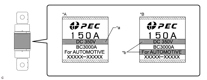
Text in Illustration *A Type A *B Type B *a Number of horizontal lines: 1 *b Number of horizontal lines: 2 - Torque:
- Type A
- 5.0 N*m { 51 kgf*cm, 44 in.*lbf }
- Type B
- 6.2 N*m { 63 kgf*cm, 55 in.*lbf }
Tech Tips
The type of the electric vehicle fuse (A or B) can be confirmed by the number of horizontal lines indicated on its label.
-
-
INSTALL NO. 2 HYBRID VEHICLE SUPPLY STACK SUB-ASSEMBLY
CAUTION:
Be sure to wear insulated gloves and protective goggles.
Note
Before installing a new hybrid vehicle supply stack sub-assembly, the voltage should be adjusted to the appropriate value.
-
Install the No. 2 hybrid vehicle supply stack sub-assembly with the 4 nuts.
- Torque:
- 19 N*m { 194 kgf*cm, 14 ft.*lbf }
-
Install the 2 No. 2 hybrid vehicle battery shield reinforcements with the 6 bolts.
- Torque:
- 11 N*m { 112 kgf*cm, 8 ft.*lbf }
Tech Tips
Install the center bolt first.
-
Install the No. 1 hybrid battery exhaust duct and No. 2 hybrid battery exhaust duct with the 8 claws.
-
Install the No. 5 hybrid battery exhaust duct and No. 6 hybrid battery exhaust duct with the 8 claws.
-
Using an insulated tool, connect the No. 3 hybrid vehicle battery pack cable with a new bolt.
- Torque:
- 5.0 N*m { 51 kgf*cm, 44 in.*lbf }
Note
-
The terminal cover should be connected securely.
-
Make sure to connect the No. 3 hybrid vehicle battery pack cable securely. If the power switch is turned on (READY) without the No. 3 hybrid vehicle battery pack cable connected, the inner circuit of the battery smart unit will be damaged due to high voltage supplied through the battery block voltage detection circuit.
-
Using an insulated tool, connect the electric vehicle battery plug assembly with a new nut.
- Torque:
- 5.0 N*m { 51 kgf*cm, 44 in.*lbf }
Note
The terminal cover should be connected securely.
-
-
INSTALL NO. 1 HYBRID VEHICLE SUPPLY STACK SUB-ASSEMBLY
CAUTION:
Be sure to wear insulated gloves and protective goggles.
Note
Before installing a new hybrid vehicle supply stack sub-assembly, the voltage should be adjusted to the appropriate value.
-
Install the No. 1 hybrid vehicle supply stack sub-assembly with the 4 nuts.
- Torque:
- 19 N*m { 194 kgf*cm, 14 ft.*lbf }
-
Install the No. 2 hybrid vehicle battery shield reinforcement with the 3 bolts.
- Torque:
- 11 N*m { 112 kgf*cm, 8 ft.*lbf }
Tech Tips
Install the center bolt first.
-
Install the No. 1 hybrid vehicle battery shield reinforcement with the 3 bolts.
- Torque:
- 11 N*m { 112 kgf*cm, 8 ft.*lbf }
Tech Tips
Install the center bolt first.
-
Install the No. 1 hybrid battery exhaust duct and No. 2 hybrid battery exhaust duct with the 8 claws.
-
Install the No. 5 hybrid battery exhaust duct with the 4 claws.
-
Using an insulated tool, connect the No. 3 hybrid vehicle battery pack cable with a new bolt.
- Torque:
- 5.0 N*m { 51 kgf*cm, 44 in.*lbf }
Note
-
The terminal cover should be connected securely.
-
Make sure to connect the No. 3 hybrid vehicle battery pack cable securely. If the power switch is turned on (READY) without the No. 3 hybrid vehicle battery pack cable connected, the inner circuit of the battery smart unit will be damaged due to high voltage supplied through the battery block voltage detection circuit.
-
Using an insulated tool, connect the No. 1 hybrid vehicle battery pack cable with a new bolt.
- Torque:
- 5.0 N*m { 51 kgf*cm, 44 in.*lbf }
Note
The terminal cover should be connected securely.
-
-
INSTALL NO. 1 HYBRID VEHICLE BATTERY HOSE
CAUTION:
Be sure to wear insulated gloves and protective goggles.
-
Install the No. 1 hybrid vehicle battery hose with the 8 clips.
-
-
INSTALL NO. 2 HYBRID VEHICLE BATTERY HOSE
CAUTION:
Be sure to wear insulated gloves and protective goggles.
-
Install the No. 2 hybrid vehicle battery hose with the 2 clips.
-
-
INSTALL NO. 3 HYBRID BATTERY INTAKE DUCT
-
Install the No. 3 hybrid battery intake duct with the 2 clips.
-
Connect the 2 intake air temperature sensor and 4 clamps.
-
-
INSTALL NO. 4 HYBRID BATTERY INTAKE DUCT
-
Install the No. 4 hybrid battery intake duct with the 2 clips.
-
Connect the 2 intake air temperature sensor and 3 clamps.
-
-
INSTALL NO. 2 HYBRID BATTERY INTAKE DUCT
-
Install the No. 2 hybrid battery intake duct with the clip.
-
-
INSTALL NO. 1 HYBRID BATTERY INTAKE DUCT
-
Install the No. 1 hybrid battery intake duct with the clip.
-
-
INSTALL BATTERY SMART UNIT
CAUTION:
Wear insulated gloves.
-
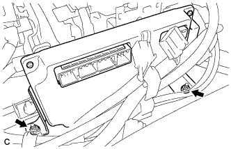
Install the battery smart unit with the 2 nuts.
- Torque:
- 8.4 N*m { 86 kgf*cm, 74 in.*lbf }
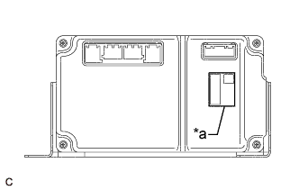
Note
Check color of the label.
Text in Illustration *a Black Label -
Be sure to connect the No. 3 hybrid vehicle battery pack cable to the correct terminals.
- Torque:
- 5.0 N*m { 51 kgf*cm, 44 in.*lbf }
Note
-
The terminal cover should be connected securely.
-
Make sure to connect the No. 3 hybrid vehicle battery pack cable securely. If the power switch is turned on (READY) without the No. 3 hybrid vehicle battery pack cable connected, the inner circuit of the battery smart unit will be damaged due to high voltage supplied through the battery block voltage detection circuit.
-
Connect the 4 connectors to the battery smart unit.
Note
Make sure that the connectors are connected securely.
-
Connect the 3 connectors to the battery smart unit.
-
-
INSTALL HYBRID BATTERY JUNCTION BLOCK ASSEMBLY
-
PERFORM UTILITY
Note
Make sure to perform "Battery Status Info Update" if the hybrid vehicle supply stack sub-assembly or HV battery is replaced Click here.