ELECTRIC VEHICLE CHARGER ASSEMBLY INSTALLATION
-
INSTALL ELECTRIC VEHICLE CHARGER SUB-ASSEMBLY
CAUTION:
Wear insulated gloves.
-
Install the plugin charge control ECU assembly with the 2 nuts to the electric vehicle charger sub-assembly.
- Torque:
- 5.5 N*m { 56 kgf*cm, 49 in.*lbf }
-
Connect the connector.
-
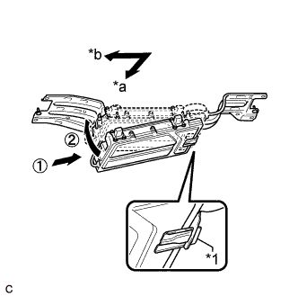
Text in Illustration *1 Bracket *a Front Side *b Left Side Install the electric vehicle charger sub-assembly to the electric vehicle charger bracket as shown in the illustration.
Note
-
Do not drop the electric vehicle charger sub-assembly.
-
Support the electric vehicle charger sub-assembly using an attachment or similar item to ensure that it does not fall.
-
Connect the bracket of the electric vehicle charger sub-assembly to the electric vehicle charger bracket.
-
Do not damage the wire harness of the electric vehicle charger sub-assembly using the electric vehicle charger bracket.
-
-
Install the 4 bolts.
- Torque:
- 8.0 N*m { 82 kgf*cm, 71 in.*lbf }
-
-
CONNECT EV CHARGE CONNECTOR BRACKET
CAUTION:
Wear insulated gloves.
-
Install the electric vehicle charge connector bracket with the 2 bolts.
- Torque:
- 8.0 N*m { 82 kgf*cm, 71 in.*lbf }
-
Connect the 2 clamps.
-
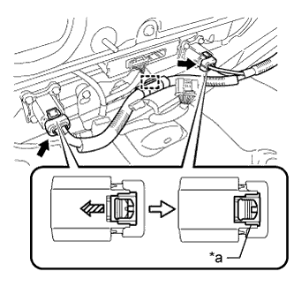
Text in Illustration *a Green-colored Lock Connect the 2 connectors and slide the 2 green-colored locks in the direction indicated by the arrow in the illustration to lock them securely.
Note
Make sure that the connectors are connected securely.
-
Connect the clamp.
-
Connect the 2 connectors and clamp.
-
-
INSTALL HYBRID BATTERY HOSE ASSEMBLY
-
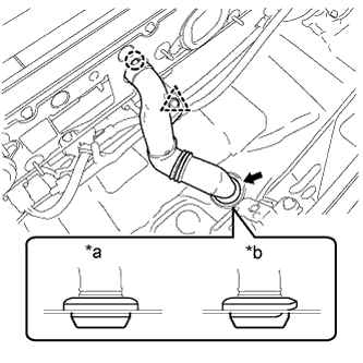
Text in Illustration *a Correct *b Incorrect Install the hybrid battery hose assembly with the claw and grommet.
Note
Make sure that there is no space or a gap between the grommet and the body.
-
Connect the clip.
-
-
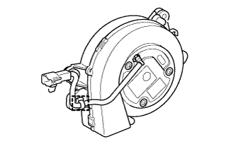
INSTALL BATTERY COOLING BLOWER ASSEMBLY (for RH Side)
Note
-
Be sure not to touch the fan part of the battery cooling blower assembly.
-
Do not lift the battery cooling blower assembly using the wire harness.
-
When replacing the battery cooling blower assembly (for RH side) with a new one:
-
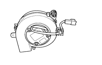
Connect the clamp to the battery cooling blower assembly (for RH side).
-
-
Install the battery cooling blower assembly with the 3 nuts.
- Torque:
- 7.5 N*m { 76 kgf*cm, 66 in.*lbf }
-
Connect the connector and clamp.
-
-
INSTALL BATTERY COOLING BLOWER ASSEMBLY (for LH Side)
Note
-
Be sure not to touch the fan part of the battery cooling blower assembly.
-
Do not lift the battery cooling blower assembly using the wire harness.
-
When replacing the battery cooling blower assembly (for LH side) with a new one:
-
Connect the clamp to the battery cooling blower assembly (for LH side).
-
-
Install the battery cooling blower assembly with the 3 nuts.
- Torque:
- 7.5 N*m { 76 kgf*cm, 66 in.*lbf }
-
Connect the connector and clamp.
-
-
INSTALL REAR DECK TRIM COVER
-
Engage the 4 claws to install the rear deck trim cover.
-
-
INSTALL DECK TRIM SERVICE HOLE COVER
-
Engage the 4 guides.
-
Engage the 4 claws to install the deck trim service hole cover.
-
-
INSTALL DECK FLOOR BOX LH
Tech Tips
Use the same procedure described for the RH side Click here.
-
INSTALL REAR NO. 4 FLOOR BOARD SUB-ASSEMBLY
-
Install the rear No. 4 floor board sub-assembly.
-
-
INSTALL REAR NO. 2 FLOOR BOARD
-
Engage the 3 fasteners.
-
Install the rear No. 2 floor board with the 2 clips.
-
-
INSTALL SERVICE PLUG GRIP