INVERTER WITH CONVERTER REMOVAL
-
PRECAUTION
-
REMOVE SERVICE PLUG GRIP
-
REMOVE FRONT SPOILER COVER (w/ Front Spoiler)
-
REMOVE FRONT LOWER BUMPER ABSORBER (w/ Cover)
-
REMOVE NO. 1 ENGINE UNDER COVER
-
DRAIN COOLANT (for Inverter)
Note
-
Do not reuse the drained coolant because it may contain foreign matter.
-
Collect the drained coolant and measure its volume to establish a benchmark. When adding coolant, make sure to add more coolant than the measured amount.
-
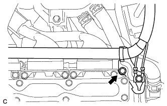
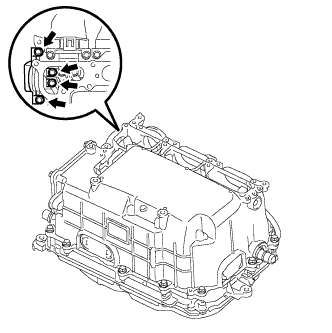
Remove the reserve tank cap.
CAUTION:
To avoid the danger of being burned, do not remove the reserve tank cap while the coolant for the inverter is still hot.
-
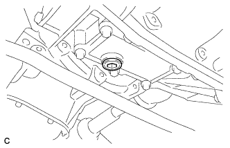
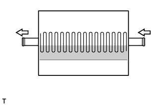
Using a hexagon wrench (10 mm), remove the drain plug indicated in the illustration and drain the coolant.
CAUTION:
Use caution when handling coolant immediately after driving or in summer because it may be hot.
-
Install the plug with a new gasket.
- Torque:
- 39 N*m { 397 kgf*cm, 29 ft.*lbf }
-
-
REMOVE RADIATOR SUPPORT OPENING COVER
-
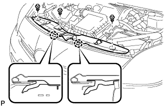
Remove the 3 clips.
-
Disengage the 2 claws and remove the radiator support opening cover.
-
-
REMOVE NO. 1 INVERTER BRACKET
-
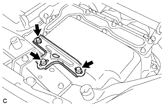
Remove the 3 bolts and No. 1 inverter bracket.
-
-
REMOVE INVERTER COVER
CAUTION:
Wear insulated gloves.
-
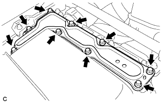
Remove the 9 bolts and inverter cover.
Note
Make sure to pull the inverter cover straight up, as a connector is connected to the bottom of the cover.
-
-
CHECK TERMINAL VOLTAGE
CAUTION:
Wear insulated gloves.
Note
Do not allow any foreign matter or water to enter the inverter with converter assembly.
-
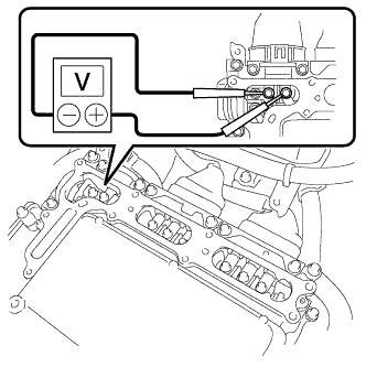
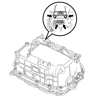
Using a voltmeter, measure the voltage between the terminals of the 2 phase connectors.
Standard voltage 0 V Tech Tips
Use measuring range of DC 750 V or more on the voltmeter.
-
-
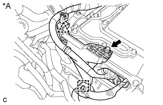
DISCONNECT ENGINE ROOM MAIN WIRE
CAUTION:
Wear insulated gloves.
Note
-
Insulate the disconnected terminals with insulating tape.
-
Cover the hole where the cable was connected with tape or equivalent (non-residue type) to prevent entry of foreign matter.
-
To prevent damage due to static electricity, do not touch the terminals of the disconnected connectors.
-
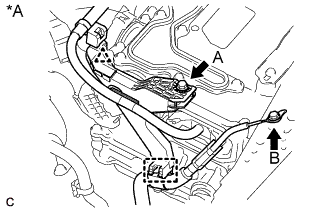
Text in Illustration *A w/ Ground Wire Remove the 2 bolts (w/ Ground Wire).
-
Disconnect the clamp and clip, and separate the engine room main wire (w/ Ground Wire).
-
Text in Illustration *A w/o Ground Wire Remove the bolt (w/o Ground wire).
-
Disconnect the clamp and clip, and separate the engine room main wire (w/o Ground Wire).
-
Raise the lock lever and disconnect the inverter with converter connector.
-
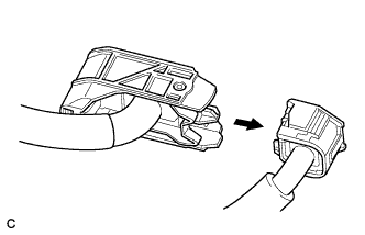
Disconnect the engine wire from the engine room main wire.
-
Remove the bolt.
-
-
DISCONNECT FRAME WIRE
CAUTION:
Wear insulated gloves.
Note
-
Insulate the disconnected terminals with insulating tape.
-
Cover the hole where the cable was connected with tape or equivalent (non-residue type) to prevent entry of foreign matter.
-
Disconnect the harness clamp.
-
Using an insulated tool, remove the 4 bolts, and disconnect the frame wire (high voltage cables of the hybrid battery) from the inverter with converter assembly.
-
-
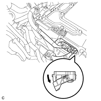
DISCONNECT GENERATOR CABLE
CAUTION:
Wear insulated gloves.
Note
-
Insulate the disconnected terminals with insulating tape.
-
Cover the hole where the cable was connected with tape or equivalent (non-residue type) to prevent entry of foreign matter.
-
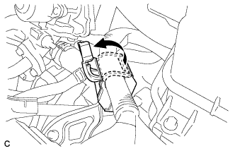
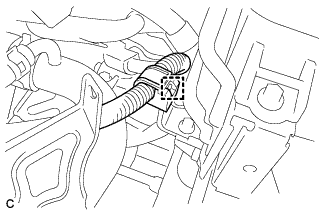
Turn back the wire harness cover and release the generator cable.
-
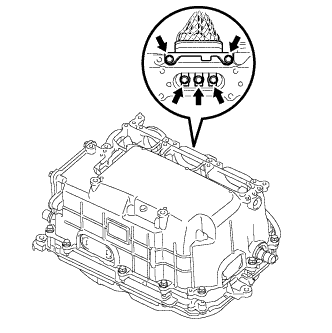
Using an insulated tool, remove the 5 bolts, and disconnect the high voltage cables of the generator cable (MG1) from the inverter with converter assembly.
-
-
DISCONNECT MOTOR CABLE
CAUTION:
Wear insulated gloves.
Note
-
Insulate the disconnected terminals with insulating tape.
-
Cover the hole where the cable was connected with tape or equivalent (non-residue type) to prevent entry of foreign matter.
-
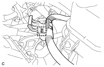
Disconnect the harness clamp.
-
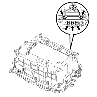
Using an insulated tool, remove the 5 bolts, and disconnect the high voltage cables of the motor cable (MG2) from the inverter with converter assembly.
-
-
DISCONNECT NO. 2 ENGINE WIRE
CAUTION:
Wear insulated gloves.
Note
-
Insulate the disconnected terminals with insulating tape.
-
Cover the hole where the cable was connected with tape or equivalent (non-residue type) to prevent entry of foreign matter.
-
Using an insulated tool, remove the 4 bolts, and disconnect the No. 2 engine wire (high voltage cables for the air conditioning compressor) from the inverter with converter assembly.
-
Disconnect the harness clamp.
-
-
INSTALL INVERTER COVER
CAUTION:
Wear insulated gloves.
-
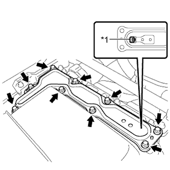
Text in Illustration *1 Interlock Temporarily install the inverter cover with the 9 bolts to prevent any foreign matter or water from entering the inverter with converter assembly.
Note
-
Make sure that the interlock is fully engaged.
-
Do not allow any foreign matter or water to enter the inverter with converter assembly.
-
-
-
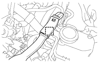
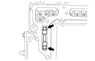
DISCONNECT NO. 2 ENGINE ROOM WIRE
-
Remove the relay block cover.
-
Release the 2 clamps, and remove the No. 1 relay block cover.
-
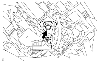
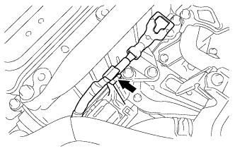
Remove the bolt from the No. 2 engine room wire.
-
Release the 2 claws, and disconnect the No. 2 engine room wire.
-
Connect the No. 2 engine room wire to the protector.
-
-
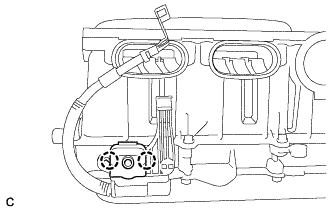
DISCONNECT NO. 1 INVERTER COOLING HOSE
-
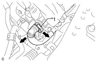
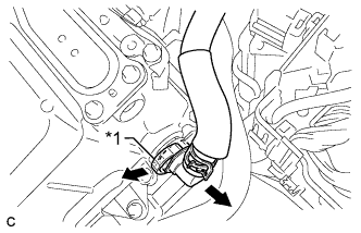
Release the retainer and disconnect the No. 1 inverter cooling hose from the inverter with converter assembly.
Text in Illustration *1 Retainer Put pieces of cloth into the pipes and in the disconnected hoses, or cover the pipes and hoses with plastic bags as shown in the illustration to prevent foreign matter from entering the cooling system and to prevent coolant from spilling near the inverter with converter assembly.
-
-
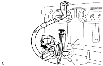
REMOVE NO. 6 INVERTER COOLING HOSE
-
Text in Illustration *1 Retainer Release the retainer and disconnect the No. 6 inverter cooling hose from the inverter with converter assembly.
-
Put pieces of cloth into the pipes and in the disconnected hoses, or cover the pipes and hoses with plastic bags as shown in the illustration to prevent foreign matter from entering the cooling system and to prevent coolant from spilling near the inverter with converter assembly.
-
-
REMOVE INVERTER WITH CONVERTER ASSEMBLY
CAUTION:
Wear insulated gloves.
-
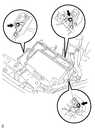
Remove the 3 bolts and inverter with converter assembly.
Note
-
Since the inverter with converter assembly is very heavy, 2 people are needed to remove the inverter with converter assembly. When removing the inverter with converter assembly, do not damage the parts around it.
-
To prevent damage, do not hold the inverter with converter assembly by the connectors.
-
To prevent damage due to static electricity, do not touch the terminals of the disconnected connectors.
-
-
Even after the coolant is drained, coolant remains in the inverter due to its internal structure. Therefore, seal or cover the pipes when removing the inverter so that coolant does not spill out.
-
-
REMOVE MOTOR CABLE BRACKET
-
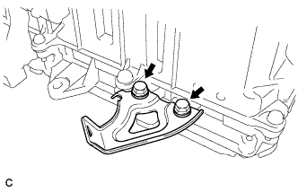
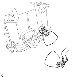
Remove the 2 bolts and motor cable bracket.
-
-
REMOVE HIGH VOLTAGE FUSE
CAUTION:
Wear insulated gloves.
Tech Tips
Perform this procedure only when replacement of the high voltage fuse is necessary.
-
Remove the 9 bolts and inverter cover.
Note
Make sure to pull the inverter cover straight up, as a connector is connected to the bottom of the cover.
-
Remove the 2 bolts and high voltage fuse from the inverter with converter assembly.
Note
Do not allow any foreign matter or water to enter the inverter with converter assembly.
-
Text in Illustration *1 Interlock Temporarily install the inverter cover with the 9 bolts to prevent any foreign matter or water from entering the inverter with converter assembly.
Note
-
Make sure that the interlock is fully engaged.
-
Do not allow any foreign matter or water to enter the inverter with converter assembly.
-
-
-
REMOVE NO. 2 ENGINE ROOM WIRE
Tech Tips
Perform this procedure only when replacement of the No. 2 engine room wire is necessary.
-
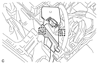
Disengage the 2 claws and open the terminal cover.
-
Remove the nut from the No. 2 engine room wire.
-
Disengage the clamp and remove the No. 2 engine room wire from the inverter with converter assembly.
-