PLUG-IN CHARGE CONTROL ECU REMOVAL
-
PRECAUTION
-
REMOVE SERVICE PLUG GRIP
-
REMOVE INVERTER COVER
CAUTION:
Wear insulated gloves.
-
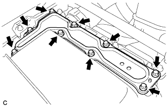
Remove the 9 bolts and inverter cover.
Note
Make sure to pull the inverter cover straight up, as a connector is connected to the bottom of the cover.
-
-
CHECK TERMINAL VOLTAGE
CAUTION:
Wear insulated gloves.
Note
Do not allow any foreign matter or water to enter the inverter with converter assembly.
-
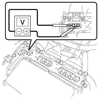
Using a voltmeter, measure the voltage between the terminals of the 2 phase connectors.
Standard voltage 0 V Tech Tips
Use measuring range of DC 750 V or more on the voltmeter.
-
-
INSTALL INVERTER COVER
CAUTION:
Wear insulated gloves.
-
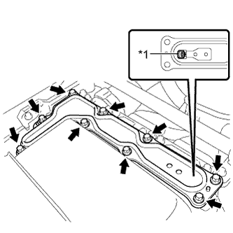
Text in Illustration *1 Interlock Install the inverter cover with the 9 bolts to the inverter with converter assembly.
- Torque:
- 11 N*m { 112 kgf*cm, 8 ft.*lbf }
Note
-
Make sure that the interlock is fully engaged.
-
Do not allow any foreign matter or water to enter the inverter with converter assembly.
-
-
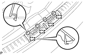
REMOVE REAR NO. 2 FLOOR BOARD
-
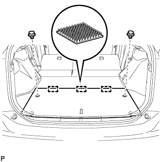
Using a clip remover, remove the 2 clips.
-
Disengage the 3 fasteners and remove the rear No. 2 floor board.
-
-
REMOVE REAR NO. 4 FLOOR BOARD SUB-ASSEMBLY
-
Remove the rear No.4 floor board sub-assembly.
-
-
REMOVE DECK FLOOR BOX LH
Tech Tips
Use the same procedure described for the RH side Click here.
-
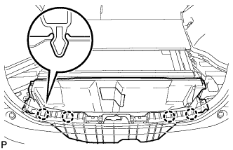
REMOVE DECK TRIM SERVICE HOLE COVER
-
Disengage the 4 claws.
-
Disengage the 4 guides and remove the deck trim service hole cover.
-
-
REMOVE REAR DECK TRIM COVER
-
Disengage the 4 claws and remove the rear deck trim cover.
-
-
REMOVE BATTERY COOLING BLOWER ASSEMBLY (for RH Side)
Note
-
Be sure not to touch the fan part of the battery cooling blower assembly.
-
Do not lift the battery cooling blower assembly using the wire harness.
-
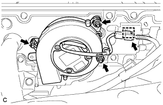
Disconnect the connector and clamp from the battery cooling blower assembly.
-
Remove the 3 nuts and battery cooling blower assembly (for RH side).
-
-
REMOVE BATTERY COOLING BLOWER ASSEMBLY (for LH Side)
Note
-
Be sure not to touch the fan part of the battery cooling blower assembly.
-
Do not lift the battery cooling blower assembly using the wire harness.
-
Disconnect the connector and clamp from the battery cooling blower assembly.
-
Remove the 3 nuts and battery cooling blower assembly (for LH side).
-
-
REMOVE HYBRID BATTERY HOSE ASSEMBLY
-
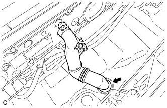
Disconnect the clip.
-
Disengage the claw.
-
Disconnect the grommet and remove the hybrid battery hose assembly.
-
-
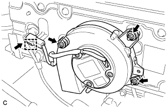
REMOVE PLUGIN CHARGE CONTROL ECU ASSEMBLY
CAUTION:
Wear insulated gloves.
-
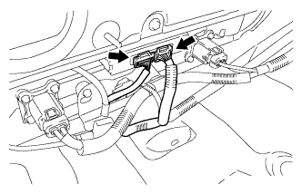
Disconnect the 2 connectors.
-
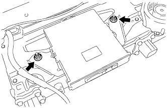
Remove the 2 nuts and plugin charge control ECU assembly.
-