HV BATTERY INSTALLATION
-
INSTALL NO. 1 HYBRID VEHICLE BATTERY MOUNT BRACKET
-
Install the No. 1 hybrid vehicle battery mount bracket with the 2 bolts.
- Torque:
- 35 N*m { 357 kgf*cm, 26 ft.*lbf }
-
-
INSTALL NO. 2 HYBRID VEHICLE BATTERY MOUNT BRACKET
-
Install the No. 2 hybrid vehicle battery mount bracket with the 2 bolts.
- Torque:
- 35 N*m { 357 kgf*cm, 26 ft.*lbf }
-
Connect the 4 clamps.
-
-
INSTALL CHILD RESTRAINT SEAT ANCHOR BRACKET SUB-ASSEMBLY RH
-
Install the child restraint seat anchor bracket sub-assembly RH with the 2 bolts.
- Torque:
- 20 N*m { 199 kgf*cm, 14 ft.*lbf }
-
Connect the clamp.
-
-
INSTALL CHILD RESTRAINT SEAT ANCHOR BRACKET SUB-ASSEMBLY LH
-
Install the child restraint seat anchor bracket sub-assembly LH with the 2 bolts.
- Torque:
- 20 N*m { 199 kgf*cm, 14 ft.*lbf }
-
-
INSTALL ELECTRIC VEHICLE CHARGER ASSEMBLY
CAUTION:
Wear insulated gloves.
-
Install the 2 electric vehicle charger brackets with the 4 bolts.
- Torque:
- 8.0 N*m { 82 kgf*cm, 71 in.*lbf }
-
Temporarily install the electric vehicle charger assembly with the 4 bolts.
-
Connect the 2 clamps.
-
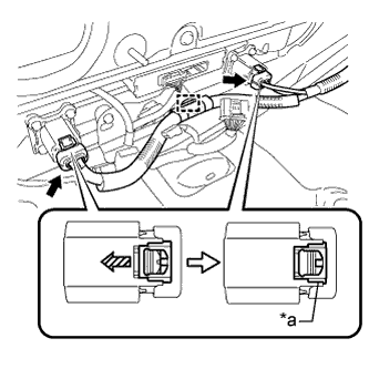
Text in Illustration *1 Green-colored Lock Connect the 2 connectors and lock the 2 green-colored locks as shown in the illustration.
Note
Make sure that the connectors are connected securely.
-
Connect the clamp.
-
Connect the 2 connectors.
-
-
INSTALL HV BATTERY
CAUTION:
Wear insulated gloves.
-
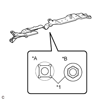
Text in Illustration *A Type A *B Type B *1 Weld Nut Check the shape of the weld nuts installed to the backside of the No. 1 or No. 2 hybrid vehicle battery mount bracket.
Tech Tips
-
Since the tightening torque of the HV battery bolts differs according to the shape of the weld nuts, it is required to check the shape before installation of the HV battery.
-
The same type of weld nuts are used to install the No. 1 and No. 2 hybrid vehicle battery mount brackets. Check the shape of a weld nut installed to either of them.
-
-
Set the 2 hooks and straps.
-
Using a suitable adaptor such as straps, install the HV battery while tilting the HV battery.
CAUTION:
To prevent any accidents and injuries due to the weight of the HV battery, follow all specified procedures and be careful to balance the HV battery when removing or installing it.
Note
-
Make sure that the HV battery does not interfere with the vehicle body during removal or installation.
-
Align the holes for the HV battery holding bolts.
-
-
Install the HV battery with the 8 bolts and 2 nuts.
- Torque:
- Nut
- 19 N*m { 194 kgf*cm, 14 ft.*lbf }
- Bolt (Type A)
- 19 N*m { 194 kgf*cm, 14 ft.*lbf }
- Bolt (Type B)
- 26 N*m { 265 kgf*cm, 19 ft.*lbf }
-
Tighten the 4 bolts.
- Torque:
- 19 N*m { 194 kgf*cm, 14 ft.*lbf }
Tech Tips
This operation should be performed when the electric vehicle charger assembly has been removed/installed.
-
Install the HV battery with the 8 bolts and 2 nuts.
- Torque:
- 19 N*m { 194 kgf*cm, 14 ft.*lbf }
-
Tighten the 4 bolts.
- Torque:
- 19 N*m { 194 kgf*cm, 14 ft.*lbf }
Tech Tips
This operation should be performed when the electric vehicle charger assembly has been removed/installed.
-
Remove the 2 bolts and 2 engine hangers (12281-28010).
-
Install the 2 bolts.
- Torque:
- 22 N*m { 224 kgf*cm, 16 ft.*lbf }
-
Connect the 4 clamps.
-
Connect the connector and 2 clamps.
-
Connect the clamp.
-
Remove the 2 bolts from each upper back door damper stay bracket.
Tech Tips
Have an assistant support the back door.
-
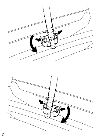
Rotate each upper back door damper stay bracket to its original position as shown in the illustration and install them with the 2 bolts.
- Torque:
- 7.5 N*m { 76 kgf*cm, 66 in.*lbf }
Tech Tips
Damage will not occur even if the back door is closed with the upper back door damper stay bracket installed upside-down. However, if this happens the open position of the back door will be higher, making operation of the back door difficult. Make sure to return the brackets to their original position after finishing work.
-
-
INSTALL NO. 2 HYBRID BATTERY INTAKE DUCT
-
Install the No. 2 hybrid battery intake duct with the clip.
-
-
INSTALL NO. 1 HYBRID BATTERY INTAKE DUCT
-
Install the No. 1 hybrid battery intake duct with the clip.
-
-
CONNECT FRAME WIRE
CAUTION:
Wear insulated gloves.
-
Connect the shield wire ground.
-
Using an insulated tool, connect the frame wire with the 2 nuts.
- Torque:
- 9.0 N*m { 92 kgf*cm, 80 in.*lbf }
-
-
CONNECT EV CHARGER WIRE
CAUTION:
Wear insulated gloves.
-
Connect the shield wire ground with the nut.
- Torque:
- 8.0 N*m { 82 kgf*cm, 71 in.*lbf }
-
Connect the connector.
Note
Make sure that the connector is connected securely.
-
-
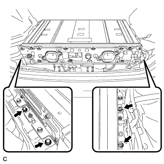
INSTALL NO. 1 HYBRID VEHICLE BATTERY SHIELD PANEL
CAUTION:
Wear insulated gloves.
-
Install the No. 1 hybrid vehicle battery shield panel with the 7 nuts.
- Torque:
- 10 N*m { 103 kgf*cm, 7 ft.*lbf }
-
Connect the connector and clamp.
-
Install the electrical key oscillator with the 2 claws and 3 clamp.
-
-
INSTALL NO. 2 HYBRID VEHICLE BATTERY SHIELD PANEL
CAUTION:
Wear insulated gloves.
-
Install the No. 2 hybrid vehicle battery shield panel with the 3 nuts.
- Torque:
- 7.5 N*m { 76 kgf*cm, 66 in.*lbf }
-
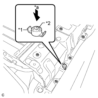
Text in Illustration *1 Battery Cover Lock Striker *2 Button *a Push Install the battery cover lock striker, then push the button to lock it.
-
-
INSTALL NO. 4 HYBRID VEHICLE BATTERY CARRIER BRACKET
-
Install the No. 4 hybrid vehicle battery carrier bracket with the bolt.
- Torque:
- 7.5 N*m { 76 kgf*cm, 66 in.*lbf }
-
-
INSTALL HYBRID BATTERY HOSE ASSEMBLY
-
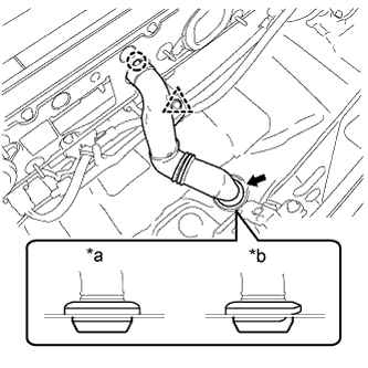
Text in Illustration *a Correct *b Incorrect Install the hybrid battery hose assembly with the claw and grommet.
Note
Make sure that there is no space or a gap between the grommet and the body.
-
Connect the clip.
-
-
INSTALL BATTERY COOLING BLOWER ASSEMBLY (for RH Side)
Note
-
Be sure not to touch the fan part of the battery cooling blower assembly.
-
Do not lift the battery cooling blower assembly using the wire harness.
-
When replacing the battery cooling blower assembly (for RH side) with a new one:
-
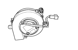
Connect the clamp to the battery cooling blower assembly (for RH side).
-
-
Install the battery cooling blower assembly with the 3 nuts.
- Torque:
- 7.5 N*m { 76 kgf*cm, 66 in.*lbf }
-
Connect the connector and clamp.
-
-
INSTALL BATTERY COOLING BLOWER ASSEMBLY (for LH Side)
Note
-
Be sure not to touch the fan part of the battery cooling blower assembly.
-
Do not lift the battery cooling blower assembly using the wire harness.
-
When replacing the battery cooling blower assembly (for LH side) with a new one:
-
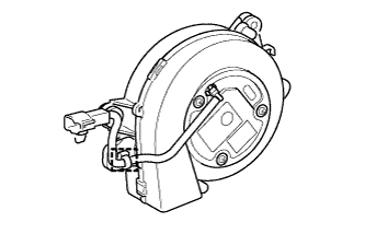
Connect the clamp to the battery cooling blower assembly (for LH side).
-
-
Install the battery cooling blower assembly with the 3 nuts.
- Torque:
- 7.5 N*m { 76 kgf*cm, 66 in.*lbf }
-
Connect the connector and clamp.
-
-
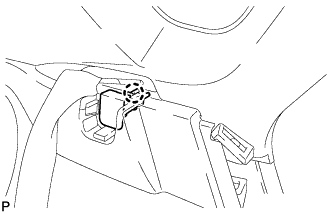
INSTALL DECK TRIM SIDE PANEL ASSEMBLY LH
-
Connect the connector.
-
Engage the 7 claws and 2 clips.
-
Install the deck trim side panel assembly LH with the screw.
-
-
INSTALL TONNEAU COVER HOLDER CAP (for LH Side)
-
Engage the claw to install the tonneau cover holder cap.
-
-
INSTALL LUGGAGE HOLD BELT STRIKER ASSEMBLY (for LH Side)
-
Engage the 2 guides.
-
Install the 2 luggage hold belt striker assemblies with the 2 bolts.
-
-
INSTALL DECK TRIM SIDE PANEL ASSEMBLY RH
-
Engage the 7 claws and 2 clips.
-
Install the deck trim side panel assembly RH with the screw.
-
-
INSTALL TONNEAU COVER HOLDER CAP (for RH Side)
Tech Tips
Use the same procedure described for the LH side.
-
INSTALL LUGGAGE HOLD BELT STRIKER ASSEMBLY (for RH Side)
Tech Tips
Use the same procedure described for the LH side.
-
INSTALL REAR SIDE SEATBACK ASSEMBLY LH
-
Engage the 2 guides as shown in the illustration.
-
Engage the 3 fasteners.
-
Install the rear side seatback assembly LH with the bolt.
- Torque:
- 18 N*m { 184 kgf*cm, 13 ft.*lbf }
-
-
INSTALL REAR SIDE SEATBACK ASSEMBLY RH
-
Engage the 2 guides as shown in the illustration.
-
Engage the 3 fasteners.
-
Install the rear side seatback assembly RH with the bolt.
- Torque:
- 18 N*m { 184 kgf*cm, 13 ft.*lbf }
-
-
INSTALL REAR SEAT CUSHION ASSEMBLY
-
Place the rear seat cushion assembly in the cabin.
Note
Be careful not to damage the vehicle body.
-
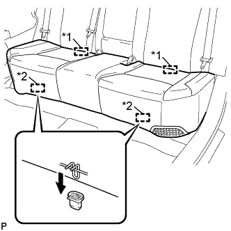
Text in Illustration *1 Rear Hook *2 Front Hook Engage the 2 rear hooks of the rear seat cushion assembly to the rear seatback assembly.
-
Engage the 2 front hooks of the rear seat cushion assembly to the vehicle body as shown in the illustration.
-
Confirm that the rear seat cushion assembly is firmly installed.
Note
When installing the rear seat cushion assembly, make sure that the seat belt buckles are not under the rear seat cushion assembly.
-
-
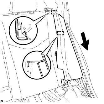
INSTALL REAR DOOR OPENING TRIM WEATHERSTRIP LH
-
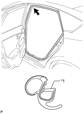
Text in Illustration *1 Alignment Mark (Red) Align the alignment mark (Red) on the weatherstrip with the protruding portion on the body indicated by the arrow in the illustration, and install the rear door opening trim weatherstrip LH.
Note
After installation, check that the corners fit correctly.
-
-
INSTALL REAR DOOR SCUFF PLATE LH
-
Engage the 7 claws to install the rear door scuff plate LH.
-
-
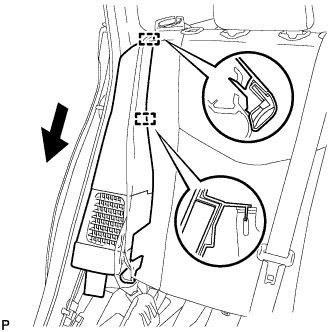
INSTALL REAR DOOR OPENING TRIM WEATHERSTRIP RH
-
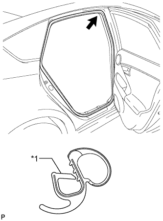
Text in Illustration *1 Alignment Mark (Blue) Align the alignment mark (Blue) on the weatherstrip with the protruding portion on the body indicated by the arrow in the illustration, and install the rear door opening trim weatherstrip RH.
Note
After installation, check that the corners fit correctly.
-
-
INSTALL REAR DOOR SCUFF PLATE RH
Tech Tips
Use the same procedure described for the LH side.
-
INSTALL REAR DECK TRIM COVER
-
Engage the 4 claws to install the rear deck trim cover.
-
-
INSTALL DECK TRIM SERVICE HOLE COVER
-
Engage the 4 guides.
-
Engage the 4 claws to install the deck trim service hole cover.
-
-
INSTALL REAR NO. 1 FLOOR BOARD
-
Engage the 3 fasteners.
-
Install the rear No. 1 floor board with the clip.
-
Engage each fastener.
-
-
INSTALL REAR NO. 1 FLOOR BOARD SUB-ASSEMBLY
-
Engage the claw and 3 clips to install the rear No. 1 floor board sub-assembly.
-
-
INSTALL REAR NO. 2 FLOOR BOARD SUB-ASSEMBLY
-
Engage the claw and 2 clips to install the rear No. 2 floor board sub-assembly.
-
-
INSTALL TONNEAU COVER ASSEMBLY
-
Install the tonneau cover assembly.
-
-
INSTALL DECK FLOOR BOX LH
Tech Tips
Use the same procedure as for the RH side Click here.
-
INSTALL REAR NO. 4 FLOOR BOARD SUB-ASSEMBLY
-
Install the rear No. 4 floor board sub-assembly.
-
-
INSTALL REAR NO. 2 FLOOR BOARD
-
Engage the 3 fasteners.
-
Install the rear No. 2 floor board with the 2 clips.
-
-
INSTALL SERVICE PLUG GRIP
-
PERFORM UTILITY
Note
Perform "Battery Status Info Update" after replacing the malfunctioning hybrid vehicle supply stack sub-assembly or HV battery Click here.