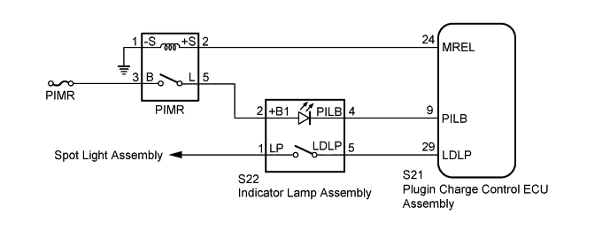
PLUG-IN CHARGE CONTROL SYSTEM Charging Indicator Circuit
DESCRIPTION
The plugin charge control ECU assembly illuminates the charging indicator to inform the driver that the vehicle is being plug-in charged. The plugin charge control ECU assembly turns off the charging indicator when the plug-in charging completes successfully. The plugin charge control ECU assembly also blinks the charging indicator if a plug-in charging malfunction occurs.
WIRING DIAGRAM
INSPECTION PROCEDURE
PROCEDURE
-
CHECK DTC OUTPUT (HEALTH CHECK)
-
Connect the GTS to the DLC3.
-
Turn the power switch on (IG).
-
Enter the following menus: Health Check.
-
Check for DTCs.
Result Result Proceed to No DTCs are output. A DTCs are output. B -
Turn the power switch off.
B 
GO TO DTC CHART
A 
-
-
READ VALUE USING GTS (CHARGE LID SW)
-
Connect the GTS to the DLC3.
-
Turn the power switch on (IG).
-
Enter the following menus: Powertrain / Plug-in Control / Data List / Charge Lid SW.
-
Read the value displayed on the GTS.
Result Tester Display Condition Normal Condition Charge Lid SW Charging port lid open ON Charging port lid close OFF OK The Data List values change in accordance with the status of the charging port lid. -
Turn the power switch off.
NG
GO TO LIGHTING SYSTEM Click here
OK
-
-
READ VALUE USING GTS (CHARGE INDICATOR LIGHT STATUS)
-
Connect the GTS to the DLC3.
-
Turn the power switch on (IG).
-
Enter the following menus: Powertrain / Plug-in Control / Data List / Charge Indicator Light Status.
-
Read the value displayed on the GTS.
Result Tester Display Condition Normal Condition Charge Indicator Light Status During plug-in charging 3: Charging indicator illuminated Plug-in charging not being performed or has completed successfully 0: Charging Indicator turned off Plug-in charging malfunction 1: Charging Indicator blinking in short intervals
2: Charging indicator blinking in long intervals
OK Operation of the charging indicator matches the display of the Data List. -
Turn the power switch off.
NG 
INSPECT INDICATOR LAMP ASSEMBLY (CHARGING INDICATOR) Click here
OK 
GO TO PROBLEM SYMPTOMS TABLE Click here
-
-
INSPECT INDICATOR LAMP ASSEMBLY (CHARGING INDICATOR)
-
Remove the indicator lamp assembly.
-
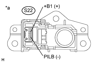
Text in Illustration *a Component without harness connected
(Indicator Lamp Assembly)
Check the charging indicator.
Result Tester Connection Condition Specified Condition S22-2 (+B1) - S22-4 (PILB) Auxiliary battery positive (+) → Terminal S22-2 (+B1)
Auxiliary battery negative (-) → Terminal S22-4 (PILB)
Charging indicator illuminates Auxiliary battery voltage is not applied between terminals S22-2 (+B1) and S22-4 (PILB) Charging indicator not illuminates -
Install the indicator lamp assembly.
NG
REPLACE INDICATOR LAMP ASSEMBLY Click here
OK
-
-
CHECK HARNESS AND CONNECTOR (PIMR RELAY - INDICATOR LAMP ASSEMBLY)
-
Disconnect the S22 indicator lamp assembly connector.
-
Turn the power switch on (IG).
-
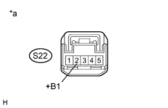
Text in Illustration *a Front view of wire harness connector
(to Indicator Lamp Assembly)
Measure the voltage according to the value(s) in the table below.
Standard Voltage Tester Connection Condition Specified Condition S22-2 (+B1) - Body ground Power switch on (IG) 11 to 14 V -
Turn the power switch off.
-
Reconnect the S22 indicator lamp assembly connector.
NG
REPAIR OR REPLACE HARNESS OR CONNECTOR
OK
-
-
CHECK HARNESS AND CONNECTOR (INDICATOR LAMP ASSEMBLY - PLUGIN CHARGE CONTROL ECU ASSEMBLY)
-
Disconnect the S22 indicator lamp assembly connector.
-
Disconnect the S21 plugin charge control ECU assembly connector.
-
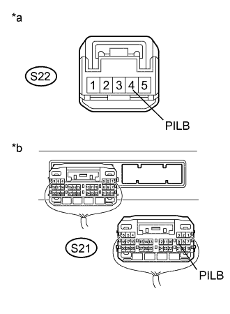
Text in Illustration *a Front view of wire harness connector
(to Indicator Lamp Assembly)
*b Rear view of wire harness connector
(to Plugin Charge Control ECU Assembly)
Measure the resistance according to the value(s) in the table below.
Standard Resistance Tester Connection Condition Specified Condition S22-4 (PILB) - S21-9 (PILB) Power switch off Below 1 Ω S22-4 (PILB) or S21-9 (PILB) - Body ground and other terminals Power switch off 10 kΩ or higher -
Reconnect the S21 plugin charge control ECU assembly connector.
-
Reconnect the S22 indicator lamp assembly connector.
NG
REPAIR OR REPLACE HARNESS OR CONNECTOR
OK
CHECK FOR INTERMITTENT PROBLEMS Click here
-