PLUG-IN CHARGE CONTROL SYSTEM ECU Power Source Circuit
DESCRIPTION
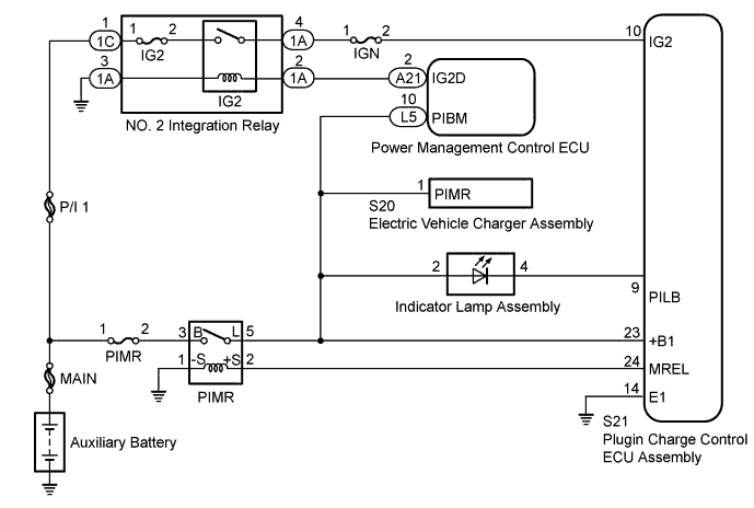
When the power switch is turned on (IG), current flows from the IG2D terminal of the power management control ECU to the IG2 relay. This closes the IG2 relay contact points and sends the IG2 signal to the IG2 terminal of the plugin charge control ECU assembly. The plugin charge control ECU assembly supplies the charging power to the +B1 terminal by allowing current to flow into the MREL terminal and closing the PIMR relay. However, during plug-in charging, only the PIMR relay is closed and the IG2 relay is open.
WIRING DIAGRAM
INSPECTION PROCEDURE
PROCEDURE
-
CHECK PLUGIN CHARGE CONTROL ECU ASSEMBLY (IG2 TERMINAL VOLTAGE)
-
Turn the power switch on (IG).
-

Text in Illustration *a Component with harness connected
(Plugin Charge Control ECU Assembly)
Measure the voltage according to the value(s) in the table below.
Standard Voltage Tester Connection Condition Specified Condition S21-10 (IG2) - Body ground Power switch on (IG) 11 to 14 V -
Turn the power switch off.
NG 
CHECK HARNESS AND CONNECTOR (PLUGIN CHARGE CONTROL ECU ASSEMBLY - IG2 RELAY) Click here
OK 
-
-
CHECK PLUGIN CHARGE CONTROL ECU ASSEMBLY (+B1 TERMINAL VOLTAGE)
-
Turn the power switch on (IG).
-
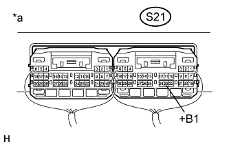
Text in Illustration *a Component with harness connected
(Plugin Charge Control ECU Assembly)
Measure the voltage according to the value(s) in the table below.
Standard Voltage Tester Connection Condition Specified Condition S21-23 (+B1) - Body ground Power switch on (IG) 11 to 14 V -
Turn the power switch off.
NG
CHECK HARNESS AND CONNECTOR (PLUGIN CHARGE CONTROL ECU ASSEMBLY - BODY GROUND) Click here
OK 
GO TO PROBLEM SYMPTOMS TABLE Click here
-
-
CHECK HARNESS AND CONNECTOR (PLUGIN CHARGE CONTROL ECU ASSEMBLY - IG2 RELAY)
-
Remove the No. 2 integration relay from the engine room relay block and junction block assembly.
-
Disconnect the S21 plugin charge control ECU assembly connector.
-
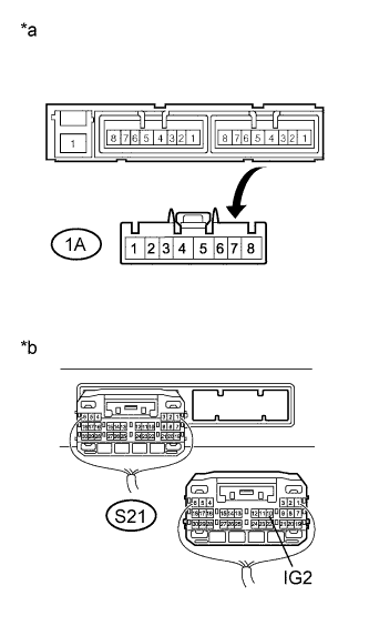
Text in Illustration *a Front view of wire harness connector
(to No. 2 Integration Relay)
*b Rear view of wire harness connector
(to Plugin Charge Control ECU Assembly)
Measure the resistance according to the value(s) in the table below.
Standard Resistance Tester Connection Condition Specified Condition 1A-4 - S21-10 (IG2) Power switch off Below 1 Ω 1A-4 or S21-10 (IG2) - Body ground and other terminals Power switch off 10 kΩ or higher -
Install the No. 2 integration relay.
-
Reconnect the S21 plugin charge control ECU assembly connector.
NG 
REPAIR OR REPLACE HARNESS OR CONNECTOR
OK
CHECK ECU POWER SOURCE CIRCUIT (HYBRID CONTROL SYSTEM) Click here
-
-
CHECK HARNESS AND CONNECTOR (PLUGIN CHARGE CONTROL ECU ASSEMBLY - BODY GROUND)
-
Disconnect the S21 plugin charge control ECU assembly connector.
-
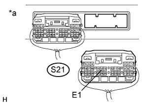
Text in Illustration *a Rear view of wire harness connector
(to Plugin Charge Control ECU Assembly)
Measure the resistance according to the value(s) in the table below.
Standard Resistance Tester Connection Condition Specified Condition S21-14 (E1) - Body ground Power switch off Below 1 Ω -
Reconnect the S21 plugin charge control ECU assembly connector.
NG
REPAIR OR REPLACE HARNESS OR CONNECTOR
OK
-
-
CHECK PLUGIN CHARGE CONTROL ECU ASSEMBLY (MREL TERMINAL VOLTAGE)
-
Turn the power switch on (IG).
-
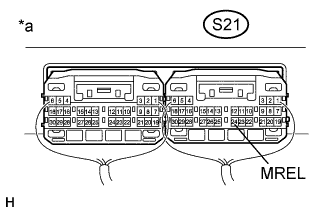
Text in Illustration *a Component with harness connected
(Plugin Charge Control ECU Assembly)
Measure the voltage according to the value(s) in the table below.
Standard Voltage Tester Connection Condition Specified Condition S21-24 (MREL) - Body ground Power switch on (IG) 11 to 14 V -
Turn the power switch off.
NG
REPLACE PLUGIN CHARGE CONTROL ECU ASSEMBLY Click here
OK
-
-
CHECK FUSE (PIMR)
-
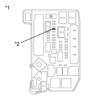
Text in Illustration *1 Engine Room Relay Block and Junction Block Assembly *2 PIMR Fuse Remove the PIMR fuse from the engine room relay block and junction block assembly.
-
Measure the resistance according to the value(s) in the table below.
Standard Resistance Tester Connection Condition Specified Condition PIMR fuse terminals Always Below 1 Ω -
Install the PIMR fuse.
NG
CHECK HARNESS AND CONNECTOR (PIMR RELAY - PIMR FUSE) Click here
OK
-
-
INSPECT RELAY (PIMR)
-
Remove the PIMR relay from the relay block assembly.
-
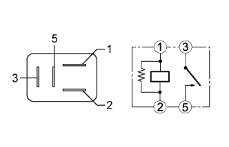
Measure the resistance according to the value(s) in the table below.
Standard Resistance Tester Connection Condition Specified Condition 3 - 5 No auxiliary battery voltage is applied across terminals 1 and 2 10 kΩ or higher Auxiliary battery voltage is applied across terminals 1 and 2 Below 1 Ω -
Install the PIMR relay.
NG
REPLACE RELAY (PIMR)
OK
-
-
CHECK HARNESS AND CONNECTOR (PIMR RELAY - PIMR FUSE)
-
Text in Illustration *1 Engine Room Relay Block and Junction Block Assembly *2 PIMR Fuse Remove the PIMR fuse from the engine room relay block and junction block assembly.
-
Remove the PIMR relay from the relay block assembly.
-
Measure the resistance according to the value(s) in the table below.
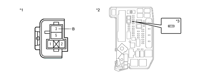
Text in Illustration *1 Relay Block Assembly (PIMR Relay) *2 Engine Room Relay Block and Junction Block Assembly *3 PIMR Fuse - - Standard Resistance Tester Connection Condition Specified Condition 3 (B) - 2 (PIMR fuse) Power switch off Below 1 Ω -
Install the PIMR relay.
-
Install the PIMR fuse.
NG
REPAIR OR REPLACE HARNESS OR CONNECTOR
OK
-
-
CHECK HARNESS AND CONNECTOR (PIMR RELAY - PLUGIN CHARGE CONTROL ECU ASSEMBLY)
-
Remove the PIMR relay from the relay block assembly.
-
Disconnect connector S21 from the plugin charge control ECU assembly.
-
Measure the resistance according to the value(s) in the table below.
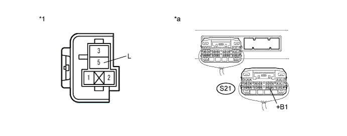
Text in Illustration *1 Relay Block Assembly (PIMR Relay) - - *a Rear view of wire harness connector
(to Plugin Charge Control ECU Assembly)
- - Standard Resistance Tester Connection Condition Specified Condition 5 (L) - S21-23 (+B1) Power switch off Below 1 Ω -
Reconnect the S21 plugin charge control ECU assembly connector.
-
Install the PIMR relay.
NG
REPAIR OR REPLACE HARNESS OR CONNECTOR
OK
-
-
CHECK HARNESS AND CONNECTOR (PIMR RELAY - PLUGIN CHARGE CONTROL ECU ASSEMBLY)
-
Remove the PIMR relay from the relay block assembly.
-
Disconnect the S21 plugin charge control ECU assembly connector.
-
Measure the resistance according to the value(s) in the table below.
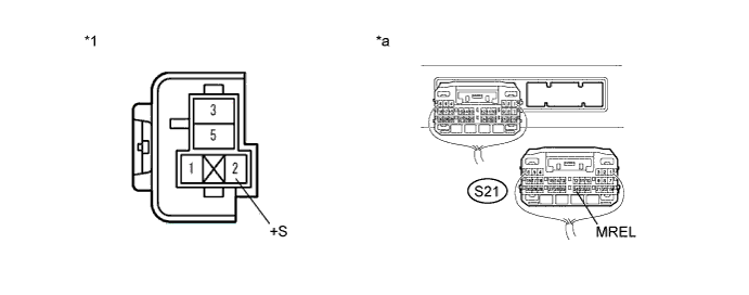
Text in Illustration *1 Relay Block Assembly (PIMR Relay) - - *a Rear view of wire harness connector
(to Plugin Charge Control ECU Assembly)
- - Standard Resistance Tester Connection Condition Specified Condition 2 (+S) - S21-24 (MREL) Power switch off Below 1 Ω 2 (+S) or S21-24 (MREL) - Body ground and other terminals Power switch off 10 kΩ or higher -
Reconnect the S21 plugin charge control ECU assembly connector.
-
Install the PIMR relay.
NG
REPAIR OR REPLACE HARNESS OR CONNECTOR
OK
-
-
CHECK HARNESS AND CONNECTOR (PIMR RELAY - BODY GROUND)
-
Remove the PIMR relay from the relay block assembly.
-
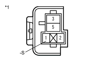
Text in Illustration *1 Relay Block Assembly (PIMR Relay) Measure the resistance according to the value(s) in the table below.
Standard Resistance Tester Connection Condition Specified Condition 1 (-S) - Body ground Power switch off Below 1 Ω -
Install the PIMR relay.
NG
REPAIR OR REPLACE HARNESS OR CONNECTOR
OK
CHECK FOR INTERMITTENT PROBLEMS Click here
-
-
CHECK HARNESS AND CONNECTOR (PIMR RELAY - PIMR FUSE)
-
Text in Illustration *1 Engine Room Relay Block and Junction Block Assembly *2 PIMR Fuse Remove the PIMR fuse from the engine room relay block and junction block assembly.
-
Remove the PIMR relay from the relay block assembly.
-
Measure the resistance according to the value(s) in the table below.
Text in Illustration *1 Relay Block Assembly (PIMR Relay) *2 Engine Room Relay Block and Junction Block Assembly *3 PIMR Fuse - - Standard Resistance Tester Connection Condition Specified Condition 3 (B) or 2 (PIMR fuse) - Body ground and other terminals Power switch off 10 kΩ or higher -
Install the PIMR relay.
-
Install the PIMR fuse.
NG
REPAIR OR REPLACE HARNESS OR CONNECTOR Click here
OK
-
-
CHECK HARNESS AND CONNECTOR (PIMR RELAY - PLUGIN CHARGE CONTROL ECU ASSEMBLY)
-
Remove the PIMR relay from the relay block assembly.
-
Disconnect the S21 plugin charge control ECU assembly connector.
-
Measure the resistance according to the value(s) in the table below.

Text in Illustration *1 Relay Block Assembly (PIMR Relay) - - *a Rear view of wire harness connector
(to Plugin Charge Control ECU Assembly)
- - Standard Resistance Tester Connection Condition Specified Condition 5 (L) or S21-23 (+B1) - Body ground and other terminals Power switch off 10 kΩ or higher -
Install the PIMR relay.
-
Reconnect the S21 plugin charge control ECU assembly connector.
NG
REPAIR OR REPLACE HARNESS OR CONNECTOR Click here
OK
REPLACE FUSE (PIMR)
-
-
REPAIR OR REPLACE HARNESS OR CONNECTOR
NEXT
REPLACE FUSE (PIMR)
-
REPAIR OR REPLACE HARNESS OR CONNECTOR
NEXT
REPLACE FUSE (PIMR)