PLUG-IN CHARGE CONTROL SYSTEM Control Pilot Signal Circuit
DESCRIPTION
The plugin charge control ECU assembly detects that the charging cable has been connected using the CPLT signal (control pilot signal). And then it starts the plug-in charge control system and changes the voltage of the CPLT signal (control pilot signal). Using the waveform duty ratio of the CPLT signal (control pilot signal), the plugin charge control ECU assembly recognizes the rated amperage of a charging facility (a socket using a charging cable) or charging stand. By changing the voltage of the CPLT signal (control pilot signal), the plulgin charge control ECU assembly transmits the status that the vehicle is ready to start charging, to the charging cable (CCID unit).
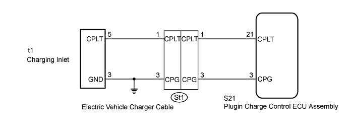
WIRING DIAGRAM
INSPECTION PROCEDURE
PROCEDURE
-
READ VALUE USING GTS (CPLT PULSE TIME, CPLT OUTPUT VOLTAGE)
Note
If the power switch is turned on (IG) during plug-in charging, the power switch will be turned off automatically after several tens of seconds.
-
Using the electric vehicle charger cable assembly, plug-in charge the vehicle.
-
Connect the GTS to the DLC3.
-
Turn the power switch on (IG).
-
Enter the following menus: Powertrain / Plug-in Control / Data List / CPLT Pulse Time, CPLT Output Voltage.
-
Read the value displayed on the GTS.
Tester Display Measurement Item/Range Normal Condition CPLT Pulse Time Duration of 1 cycle of CPLT/
Min.: 0 μs, Max.: 65535 μs
980 to 1020 μs: CPLT (control pilot signal) generated CPLT Output Voltage CPLT terminal voltage/
Min.: 0.0 V, Max.: 25.5 V
8 to 10 V: Connected, not ready to receive power
5 to 7 V: Connected, ready to receive power, indoor charging ventilation not required
3 V: Connected, ready to receive power, indoor charging ventilation required
0 V: Not connected to the EVSE (charging stand) system or power unavailable
OK Data List values are within the specified range. -
Turn the power switch off.
-
Disconnect the electric vehicle charger cable assembly.
NG 
CHECK HARNESS AND CONNECTOR (CHARGING INLET - PLUGIN CHARGE CONTROL ECU ASSEMBLY) Click here
OK 
GO TO PROBLEM SYMPTOMS TABLE Click here
-
-
CHECK HARNESS AND CONNECTOR (CHARGING INLET - PLUGIN CHARGE CONTROL ECU ASSEMBLY)
-
Open the charging port lid.
-
Disconnect the S21 plugin charge control ECU assembly connector.
-
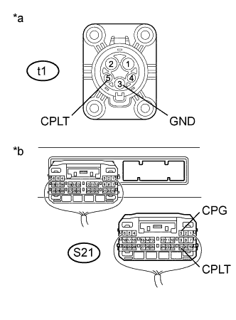
Text in Illustration *a Electric Vehicle Charger Cable
(Charging Inlet Side)
*b Rear view of wire harness connector
(to Plugin Charge Control ECU Assembly)
Measure the resistance according to the value(s) in the table below.
Standard Resistance Tester Connection Condition Specified Condition t1-5 (CPLT) - S21-21 (CPLT) Power switch off Below 1 Ω t1-3 (GND) and S21-3 (CPG) - Body ground Power switch off Below 1 Ω t1-5 (CPLT) or S21-21 (CPLT) - Body ground and other terminals Power switch off 10 kΩ or higher t1-3 (GND) or S21-3 (CPG) - other terminals Power switch off 10 kΩ or higher -
Turn the power switch on (IG).
-
Measure the voltage according to the value(s) in the table below.
Standard Voltage Tester Connection Condition Specified Condition t1-4 (CPLT) or S21-21 (CPLT) - Body ground Power switch on (IG) Below 1 V Note
Turning the power switch on (IG) with the plugin charge control ECU assembly connector disconnected causes other DTCs to be stored. Clear the DTCs after performing this inspection.
-
Turn the power switch off.
-
Reconnect the S21 plugin charge control ECU assembly connector.
-
Close the charging port lid.
NG
CHECK HARNESS AND CONNECTOR (ELECTRIC VEHICLE CHARGER CABLE - PLUGIN CHARGE CONTROL ECU ASSEMBLY) Click here
OK 
-
-
CHECK ELECTRIC VEHICLE CHARGER CABLE ASSEMBLY (CPLT TERMINAL VOLTAGE)
CAUTION:
Be sure to wear insulated gloves.
-
Connect the electric vehicle charger cable assembly to a socket.
Tech Tips
Do not connect the electric vehicle charger cable assembly to the vehicle side charging inlet.
-
Check the condition of the power and error warning indicators on the electric vehicle charger cable assembly.
OK Condition Specified Condition Power Indicator Error Warning Indicator Connect the electric vehicle charger cable assembly to a socket Illuminated Turns off or blinks (continuously) Tech Tips
For details on the status of the power and error warning indicators, refer to Charge Cable On-vehicle Inspection Click here.
-
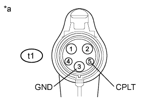
Text in Illustration *a Electric Vehicle Charger Cable Assembly
(Charging Connector Side)
Measure the voltage according to the value(s) in the table below.
Standard Voltage Tester Connection Condition Specified Condition t1-5 (CPLT) - t1-3 (GND) Electric vehicle charger cable assembly connected to a socket 11.4 to 12.6 V -
Disconnect the electric vehicle charger cable assembly from the socket.
NG 
REPLACE ELECTRIC VEHICLE CHARGER CABLE ASSEMBLY
OK
REPLACE PLUGIN CHARGE CONTROL ECU ASSEMBLY Click here
-
-
CHECK HARNESS AND CONNECTOR (ELECTRIC VEHICLE CHARGER CABLE - PLUGIN CHARGE CONTROL ECU ASSEMBLY)
-
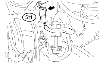
Disconnect the St1 electric vehicle charger cable connector.
-
Disconnect the S21 plugin charge control ECU assembly connector.
-
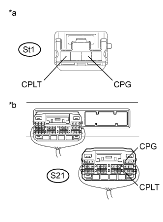
Text in Illustration *a Front view of wire harness connector
(to Electric Vehicle Charger Cable)
*b Rear view of wire harness connector
(to Plugin Charge Control ECU Assembly)
Measure the resistance according to the value(s) in the table below.
Standard Resistance Tester Connection Condition Specified Condition St1-1 (CPLT) - S21-21 (CPLT) Power switch off Below 1 Ω St1-3 (CPG) - S21-3 (CPG) Power switch off Below 1 Ω St1-1 (CPLT) or S21-21 (CPLT) - Body ground and other terminals Power switch off 10 kΩ or higher St1-3 (CPG) or S21-3 (CPG) - other terminals Power switch off 10 kΩ or higher -
Turn the power switch on (IG).
-
Measure the voltage according to the value(s) in the table below.
Standard Voltage Tester Connection Condition Specified Condition St1-1 (CPLT) or S21-21 (CPLT) - Body ground Power switch on (IG) Below 1 V Note
Turning the power switch on (IG) with the plugin charge control ECU assembly connector disconnected causes other DTCs to be stored. Clear the DTCs after performing this inspection.
-
Turn the power switch off.
-
Reconnect the S21 plugin charge control ECU assembly connector.
-
Reconnect the St1 electric vehicle charger cable connector.
NG
REPAIR OR REPLACE HARNESS OR CONNECTOR
OK
REPAIR OR REPLACE ELECTRIC VEHICLE CHARGER CABLE Click here
-