PLUG-IN CHARGE CONTROL SYSTEM Open in AC Line
WIRING DIAGRAM
Refer to the wiring diagram for DTC P0D3F-235 Click here.
Refer to the wiring diagram for DTC P0D5C-847 Click here.
INSPECTION PROCEDURE
CAUTION:
-
Before inspecting the high-voltage system or disconnecting the low voltage connector of the inverter with converter assembly or electric vehicle charger assembly, turn the power switch off. Also, take safety precautions such as wearing insulated gloves and removing the service plug grip to prevent electrical shocks. After removing the service plug grip, put it in your pocket to prevent other technicians from accidentally reconnecting it while you are working on the high-voltage system.
-
After removing the service plug grip, wait for at least 10 minutes before touching any of the high-voltage connectors or terminals. After waiting for 10 minutes, check the voltage at the terminals in the inspection point in the inverter with converter assembly. The voltage should be 0 V before beginning work Click here.
Tech Tips
Waiting for at least 10 minutes is required to discharge the high-voltage capacitor inside the inverter with converter assembly and electric vehicle charger assembly.
Note
After turning the power switch off, waiting time may be required before disconnecting the cable from the negative (-) auxiliary battery terminal. Therefore, make sure to read the disconnecting the cable from the negative (-) auxiliary battery terminal notices before proceeding with work Click here.
PROCEDURE
-
CHECK ELECTRIC VEHICLE CHARGER CABLE ASSEMBLY (CONNECTION CONDITION)
-
Visual inspection
-
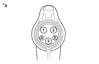
Text in Illustration *a Electric Vehicle Charger Cable Assembly
(Charging Connector Side)
Check if any foreign matter is attached to the connecting part of the electric vehicle charger cable assembly.
-
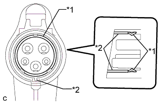
Text in Illustration *1 EV Charge Connector Seal *2 EV Charge Connector Retainer Check the installation condition of the EV charge connector seal.
Note
If the EV charge connector seal is loose, replace the EV charge connector seal and EV charge connector retainer.
-
-
Check the latch release button (PISW)
-
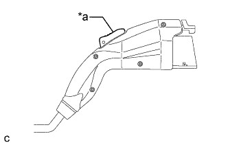
Text in Illustration *a Latch Release Button (PISW) Check that the latch release button (PISW) can be pressed with no abnormal resistance.
-
-
Check connection
-
Check that the electric vehicle charger cable assembly and electric vehicle charger cable (charging inlet side) can be connected smoothly.
OK The electric vehicle charger cable assembly and electric vehicle charger cable (charging inlet side) connect smoothly. Tech Tips
If the result is not as specified, perform the following checks.
-
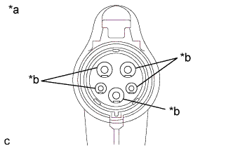
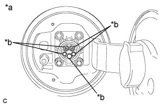
Text in Illustration *a Electric Vehicle Charger Cable Assembly
(Charging Connector Side)
*b Terminal Check that the terminals of the electric vehicle charger cable assembly (charging connector side) are not bent or deformed.
OK The terminals are not bent or deformed. Tech Tips
If the result is not as specified, replace the electric vehicle charger cable assembly.
-
Text in Illustration *a Electric Vehicle Charger Cable
(Charging Connector Side)
*b Terminal Check that the terminals of the electric vehicle charger cable (charging inlet side) are not bent or deformed.
OK The terminals are not bent or deformed. Tech Tips
-
If the electric vehicle charger cable assembly (charging connector side) is connected to the electric vehicle charger cable (charging inlet side) incorrectly, the terminals may be bent or deformed.
-
If the result is not as specified, replace the electric vehicle charger cable.
-
-
NG 
REPLACE MALFUNCTIONING PARTS
OK 
-
-
CHECK ELECTRIC VEHICLE CHARGER CABLE (CHARGING INLET - ELECTRIC VEHICLE CHARGER WIRE CONNECTOR)
CAUTION:
Be sure to wear insulated gloves.
-
Check that the service plug grip is not installed.
Note
After removing the service plug grip, do not turn the power switch on (READY), unless instructed by the repair manual because this may cause a malfunction.
-
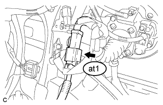
Disconnect the at1 electric vehicle charger wire connector Click here.
-
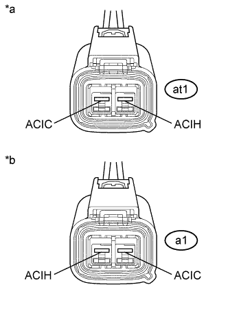
Text in Illustration *a Electric Vehicle Charger Cable
(Charging Inlet Side)
*b Electric Vehicle Charger Cable
(Electric Vehicle Charger Wire Side)
Measure the resistance according to the value(s) in the table below.
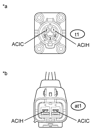
Standard Resistance Tester Connection Condition Specified Condition t1-2 (ACIC) - at1-1 (ACIC) Power switch off Below 1 Ω t1-1 (ACIH) - at1-2 (ACIH) Power switch off Below 1 Ω -
Reconnect the at1 electric vehicle charger wire connector.
NG
REPLACE ELECTRIC VEHICLE CHARGER CABLE Click here
OK
-
-
CHECK ELECTRIC VEHICLE CHARGER WIRE (ELECTRIC VEHICLE CHARGER WIRE CONNECTOR - ELECTRIC VEHICLE CHARGER ASSEMBLY)
CAUTION:
Be sure to wear insulated gloves.
-
Check that the service plug grip is not installed.
Note
After removing the service plug grip, do not turn the power switch on (READY), unless instructed by the repair manual because this may cause a malfunction.
-
Disconnect the at1 electric vehicle charger wire connector Click here.
-
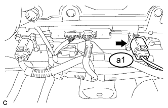
Disconnect the a1 electric vehicle charger assembly connector Click here.
-
Text in Illustration *a Electric Vehicle Charger Wire
(Electric Vehicle Charger Cable Side)
*b Electric Vehicle Charger Wire
(Electric Vehicle Charger Assembly Side)
Measure the resistance according to the value(s) in the table below.
Standard Resistance Tester Connection Condition Specified Condition at1-1 (ACIC) - a1-2 (ACIC) Power switch off Below 1 Ω at1-2 (ACIH) - a1-1 (ACIH) Power switch off Below 1 Ω -
Reconnect the a1 electric vehicle charger assembly connector.
-
Reconnect the at1 electric vehicle charger wire connector.
NG
REPLACE EV CHARGER WIRE Click here
OK
-
-
CHECK ELECTRIC VEHICLE CHARGER ASSEMBLY (VAC SENSOR OUTPUT VOLTAGE)
CAUTION:
Be sure to wear insulated gloves.
-
Check that the service plug grip is not installed.
Note
After removing the service plug grip, do not turn the power switch on (READY), unless instructed by the repair manual because this may cause a malfunction.
-
Disconnect the z12 plugin charge control ECU assembly connector.
-
Connect the cable to the negative (-) auxiliary battery terminal.
-
Turn the power switch on (IG).
-
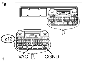
Text in Illustration *a Rear view of wire harness connector
(to Plugin Charge Control ECU Assembly)
Measure the voltage according to the value(s) in the table below.
Standard Voltage Tester Connection Condition Specified Condition z12-23 (VAC) - z12-21 (CGND) Power switch on (IG) 5.0 to 6.0 V Tech Tips
Turning the power switch on (IG) with the plugin charge control ECU assembly connector disconnected causes other DTCs to be stored. Clear the DTCs after performing this inspection.
-
Turn the power switch off.
-
Disconnect the cable from the negative (-) auxiliary battery terminal.
-
Reconnect the z12 plugin charge control ECU assembly connector.
NG
REPLACE ELECTRIC VEHICLE CHARGER ASSEMBLY Click here
OK 
REPLACE PLUGIN CHARGE CONTROL ECU ASSEMBLY Click here
-