PLUG-IN CHARGE CONTROL SYSTEM Charging Timer Switch Circuit
DESCRIPTION
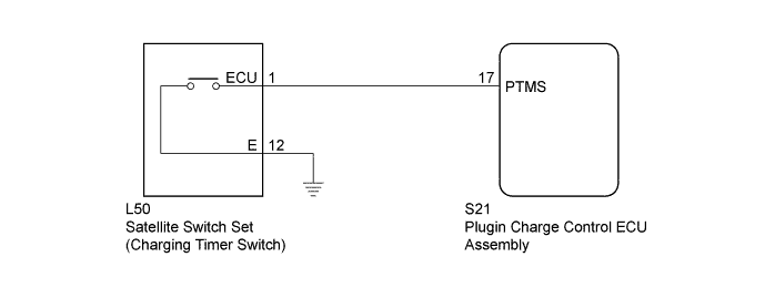
Based on the signal from the satellite switch set (charging timer switch), the plugin charge control ECU assembly changes on/off status of the charging timer function and changes the mode to charging timer setting mode.
WIRING DIAGRAM
INSPECTION PROCEDURE
PROCEDURE
-
READ VALUE USING GTS (CHARGING TIMER SW)
-
Connect the GTS to the DLC3.
-
Turn the power switch on (IG).
-
Enter the following menus: Powertrain / Plug-in Control / Data List / Charging Timer SW.
-
Read the value displayed on the GTS.
Tester Display Measurement Item/Range Normal Condition Charging Timer SW Charging timer switch status/
ON or OFF
ON: Charging timer switch operated
OFF: Charging timer switch not operated
OK The Data List values change in accordance with the status of charging timer switch. -
Turn the power switch off.
NG 
INSPECT SATELLITE SWITCH SET (CHARGING TIMER SWITCH CHECK) Click here
OK 
GO TO PROBLEM SYMPTOMS TABLE Click here
-
-
INSPECT SATELLITE SWITCH SET (CHARGING TIMER SWITCH CHECK)
-
Remove the satellite switch set.
-
Measure the resistance according to the value(s) in the table below.
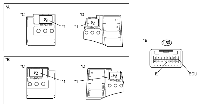
Text in Illustration *1 Charging Timer Switch - - *A for LHD *B for RHD *C w/o Headup Display *D w/ Headup Display *a Component without harness connected
(Satellite Switch Set)
- - Standard Resistance Tester Connection Condition Specified Condition L50-1 (ECU) - L50-12 (E) Charging timer switch operated Below 1 Ω Charging timer switch not operated 10 kΩ or higher -
Install the satellite switch set.
NG 
REPLACE SATELLITE SWITCH SET Click here
OK 
-
-
CHECK HARNESS AND CONNECTOR (SATELLITE SWITCH SET - PLUGIN CHARGE CONTROL ECU ASSEMBLY)
-
Disconnect the L50 satellite switch set connector.
-
Disconnect the S21 plugin charge control ECU assembly connector.
-
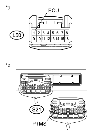
Text in Illustration *a Front view of wire harness connector
(to Satellite Switch Set)
*b Rear view of wire harness connector
(to Plugin Charge Control ECU Assembly)
Measure the resistance according to the value(s) in the table below.
Standard Resistance Tester Connection Condition Specified Condition L50-1 (ECU) - S21-17 (PTMS) Power switch off Below 1 Ω L50-1 (ECU) or S21-17 (PTMS) - Body ground and other terminals Power switch off 10 kΩ or higher -
Reconnect the S21 plugin charge control ECU assembly connector.
-
Reconnect the L50 satellite switch set connector.
NG
REPAIR OR REPLACE HARNESS OR CONNECTOR
OK
-
-
CHECK HARNESS AND CONNECTOR (SATELLITE SWITCH SET - BODY GROUND)
-
Disconnect the L50 satellite switch set connector.
-
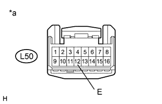
Text in Illustration *a Front view of wire harness connector
(to Satellite Switch Set)
Measure the resistance according to the value(s) in the table below.
Standard Resistance Tester Connection Condition Specified Condition L50-12 (E) - Body ground Power switch off Below 1 Ω -
Reconnect the L50 satellite switch set connector.
NG
REPAIR OR REPLACE HARNESS OR CONNECTOR
OK
CHECK FOR INTERMITTENT PROBLEMS Click here
-