PLUG-IN CHARGE CONTROL SYSTEM Charging Timer Indicator Circuit
DESCRIPTION
By sending the on/off status of the charging timer function to the combination meter assembly, the plugin charge control ECU assembly turns on/off the charging timer indicator.
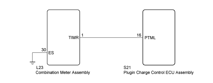
WIRING DIAGRAM
INSPECTION PROCEDURE
PROCEDURE
-
READ VALUE USING GTS (CHARGING TIMER SW)
-
Connect the GTS to the DLC3.
-
Turn the power switch on (IG).
-
Enter the following menus: Powertrain / Plug-in Control / Data List / Charging Timer SW.
-
Read the value displayed on the GTS.
Tester Display Measurement Item/Range Normal Condition Charging Timer SW Charging timer switch status/
ON or OFF
ON: Charging timer switch operated
OFF: Charging timer switch not operated
OK The Data List values change in accordance with the status of charging timer switch. -
Turn the power switch off.
NG 
GO TO PROBLEM SYMPTOMS TABLE Click here
OK 
-
-
READ VALUE USING GTS (TIMER LAMP LIGHT REQUEST)
-
Connect the GTS to the DLC3.
-
Turn the power switch on (IG).
-
Enter the following menus: Powertrain / Plug-in Control / Data List / Timer Lamp Light Request.
-
Set the charging timer and check the Data List item "Timer Lamp Light Request" ON/OFF status and the charging timer indicator illumination in the combination meter assembly.
Tester Display Measurement Item/Range Normal Condition Timer Lamp Light Request Charging timer indicator illumination status/
ON or OFF
ON: Charging timer indicator illuminated
OFF: Charging timer indicator not illuminated
Result Result Proceed to The Data List values and on/off status of the charging timer indicator change in accordance with the setting of the charging timer function. A Although the Data List values change, on/off status of the charging timer indicator does not change in accordance with the setting of the charging timer function. B The Data List values do not change in accordance with the setting of the charging timer function. C -
Turn the power switch off.
B 
CHECK HARNESS AND CONNECTOR (COMBINATION METER ASSEMBLY - PLUGIN CHARGE CONTROL ECU ASSEMBLY) Click here
C
REPLACE PLUGIN CHARGE CONTROL ECU ASSEMBLY Click here
A 
CHECK FOR INTERMITTENT PROBLEMS Click here
-
-
CHECK HARNESS AND CONNECTOR (COMBINATION METER ASSEMBLY - PLUGIN CHARGE CONTROL ECU ASSEMBLY)
-
Disconnect the L23 combination meter assembly connector.
-
Disconnect the S21 plugin charge control ECU assembly connector.
-
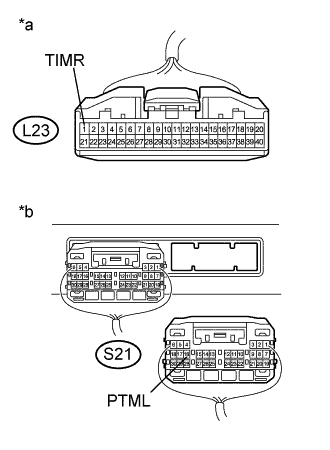
Text in Illustration *a Front view of wire harness connector
(to Combination Meter Assembly)
*b Rear view of wire harness connector
(to Plugin Charge Control ECU Assembly)
Measure the resistance according to the value(s) in the table below.
Standard Resistance Tester Connection Condition Specified Condition L23-1 (TIMR) - S21-16(PTML) Power switch off Below 1 Ω L23-1 (TIMR) or S21-16 (PTML) - Body ground Power switch off 10 kΩ or higher -
Turn the power switch on (IG).
-
Measure the voltage according to the value(s) in the table below.
Standard Voltage Tester Connection Condition Specified Condition L23-1 (TIMR) or S21-16 (PTML) - Body ground Power switch on (IG) Below 1 V Note
Turning the power switch on (IG) with the plugin charge control ECU assembly connector disconnected causes other DTCs to be stored. Clear the DTCs after performing this inspection.
-
Turn the power switch off.
-
Reconnect the S21 plugin charge control ECU assembly connector.
-
Reconnect the L23 combination meter assembly connector.
NG
REPAIR OR REPLACE HARNESS OR CONNECTOR
OK
GO TO COMBINATION METER SYSTEM Click here
-