PLUG-IN CHARGE CONTROL SYSTEM, Diagnostic DTC:U0293-439
| DTC Code | DTC Name |
|---|---|
| U0293-439 | Lost Communication with Hybrid Powertrain Control Module |
DESCRIPTION
The plugin charge control ECU assembly receives or sends a signal from or to the power management control ECU.
| DTC No. | INF Code | DTC Detection Condition | Trouble Area |
|---|---|---|---|
| U0293 | 439 | No signal has been received from/sent to the power management control ECU for a certain period of time (when the power switch is on (IG)). |
|
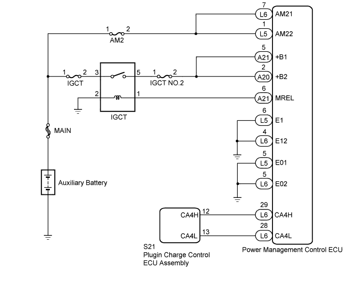
WIRING DIAGRAM
INSPECTION PROCEDURE
Tech Tips
After the repair, turn the power switch off. Wait for 10 seconds or more, turn the power switch on (IG), and check that DTCs are not output.
PROCEDURE
-
CHECK DTC OUTPUT (HEALTH CHECK)
-
Connect the GTS to the DLC3.
-
Turn the power switch on (IG).
-
Enter the following menus: System Select / Health Check.
-
Check if DTCs are output.
Result Result Proceed to Only U0293-439 is output or U0293-439 and U0293-449 are also output. A Any CAN communication system DTC other than U0293-449 is also output. B -
Turn the power switch off.
B 
GO TO CAN COMMUNICATION SYSTEM Click here
A 
-
-
CHECK HARNESS AND CONNECTOR (POWER MANAGEMENT CONTROL ECU - PLUGIN CHARGE CONTROL ECU ASSEMBLY)
-
Disconnect the L6 power management control ECU connector.
-
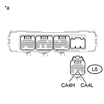
Text in Illustration *a Rear view of wire harness connector
(to Power Management Control ECU)
Measure the resistance according to the value(s) in the table below.
Standard Resistance (Check for Open) Tester Connection Condition Specified Condition L6-28 (CA4L) - L6-29 (CA4H) Power switch off 108 to 132 Ω Standard Resistance (Check for Short) Tester Connection Condition Specified Condition L6-28 (CA4L) or L6-29 (CA4H) - Body ground and other terminals Power switch off 10 kΩ or higher -
Reconnect the L6 power management control ECU connector.
NG 
CHECK HARNESS AND CONNECTOR (POWER MANAGEMENT CONTROL ECU - PLUGIN CHARGE CONTROL ECU ASSEMBLY) Click here
OK
-
-
CHECK HARNESS AND CONNECTOR (AM21, AM22 VOLTAGE)
-
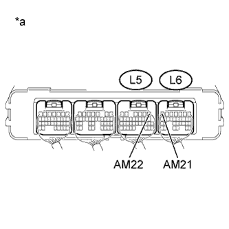
Text in Illustration *a Component with harness connected
(Power Management Control ECU)
Measure the voltage according to the value(s) in the table below.
Standard Voltage Tester Connection Condition Specified Condition L5-1 (AM22) - Body ground Power switch off 11 to 14 V L6-7 (AM21) - Body ground Power switch off 11 to 14 V
NG
CHECK FUSE (AM2) Click here
OK
-
-
CHECK POWER MANAGEMENT CONTROL ECU (+B1, +B2 VOLTAGE)
-
Turn the power switch on (IG).
-
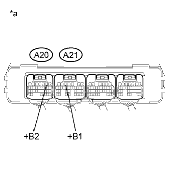
Text in Illustration *a Component with harness connected
(Power Management Control ECU)
Measure the voltage according to the value(s) in the table below.
Standard Voltage Tester Connection Condition Specified Condition A21-5 (+B1) - Body ground Power switch on (IG) 11 to 14 V A20-2 (+B2) - Body ground Power switch on (IG) 11 to 14 V -
Turn the power switch off.
NG
CHECK FOR ECU POWER SOURCE CIRCUIT Click here
OK
-
-
CHECK HARNESS AND CONNECTOR (POWER MANAGEMENT CONTROL ECU - BODY GROUND)
-
Disconnect the L5 and L6 power management control ECU connectors.
-
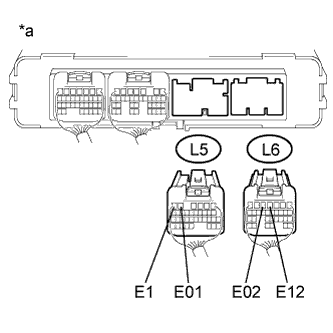
Text in Illustration *a Rear view of wire harness connector
(to Power Management Control ECU)
Measure the resistance according to the value(s) in the table below.
Standard Resistance Tester Connection Condition Specified Condition L5-5 (E01) - Body ground Always Below 1 Ω L5-6 (E1) - Body ground Always Below 1 Ω L6-4 (E12) - Body ground Always Below 1 Ω L6-5 (E02) - Body ground Always Below 1 Ω -
Reconnect the L5 and L6 power management control ECU connectors.
NG
REPAIR OR REPLACE HARNESS OR CONNECTOR
OK 
REPLACE POWER MANAGEMENT CONTROL ECU Click here
-
-
CHECK HARNESS AND CONNECTOR (POWER MANAGEMENT CONTROL ECU - PLUGIN CHARGE CONTROL ECU ASSEMBLY)
-
Disconnect the L6 power management control ECU connector.
-
Disconnect the S21 plugin charge control ECU assembly connector.
-
Measure the resistance according to the value(s) in the table below.
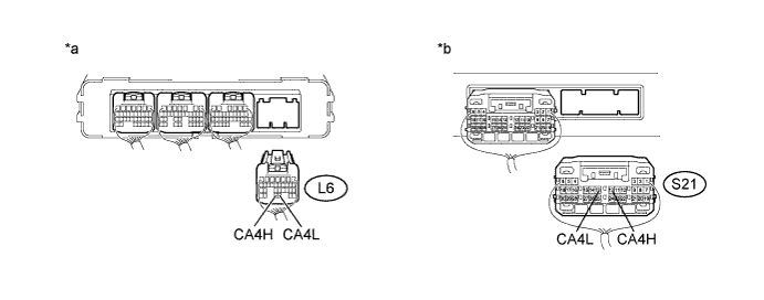
Text in Illustration *a Rear view of wire harness connector
(to Power Management Control ECU)
*b Rear view of wire harness connector
(to Plugin Charge Control ECU Assembly)
Standard Resistance (Check for Open) Tester Connection Condition Specified Condition L6-28 (CA4L) - S21-13 (CA4L) Power switch off Below 1 Ω L6-29 (CA4H) - S21-12 (CA4H) Power switch off Below 1 Ω Standard Resistance (Check for Short) Tester Connection Condition Specified Condition L6-28 (CA4L) - S21-13 (CA4L) - Body ground and other terminals Power switch off 10 kΩ or higher L6-29 (CA4H) - S21-12 (CA4H) - Body ground and other terminals Power switch off 10 kΩ or higher -
Reconnect the S21 plugin charge control ECU assembly connector.
-
Reconnect the L6 power management control ECU connector.
NG
REPAIR OR REPLACE HARNESS OR CONNECTOR
OK
REPLACE PLUGIN CHARGE CONTROL ECU ASSEMBLY Click here
-
-
CHECK FUSE (AM2)
-
Remove the AM2 fuse from the engine room relay block and junction block assembly.
-
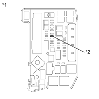
Text in Illustration *1 Engine Room Relay Block and Junction Block Assembly *2 AM2 Fuse Measure the resistance according to the value(s) in the table below.
Standard Resistance Tester Connection Condition Specified Condition AM2 fuse Always Below 1 Ω -
Install the AM2 fuse.
NG
REPLACE FUSE (AM2)
OK
-
-
CHECK HARNESS AND CONNECTOR (POWER MANAGEMENT CONTROL ECU - AM2 FUSE)
-
Disconnect the L5 and L6 power management control ECU connectors.
-
Remove the AM2 fuse from the engine room relay block and junction block assembly.
-
Measure the resistance according to the value(s) in the table below.
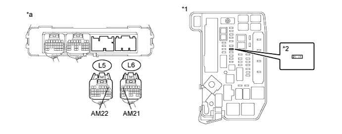
Text in Illustration *1 Engine Room Relay Block and Junction Block Assembly *2 AM2 Fuse *a Rear view of wire harness connector
(to Power Management Control ECU)
- - Standard Resistance (Check for Open) Tester Connection Condition Specified Condition L5-1 (AM22) - 2 (AM2 fuse) Power switch off Below 1 Ω L6-7 (AM21) - 2 (AM2 fuse) Power switch off Below 1 Ω Standard Resistance (Check for Short) Tester Connection Condition Specified Condition L5-1 (AM22), L6-7 (AM21) or 2 (AM2 fuse) - Body ground and other terminals Power switch off 10 kΩ or higher -
Install the AM2 fuse.
-
Reconnect the L5 and L6 power management control ECU connectors.
NG
REPAIR OR REPLACE HARNESS OR CONNECTOR
OK
CHECK POWER SOURCE CIRCUIT
-