PLUG-IN CHARGE CONTROL SYSTEM, Diagnostic DTC:P31FC-410
| DTC Code | DTC Name |
|---|---|
| P31FC-410 | On-Board Charger Status Circuit |
DESCRIPTION
Refer to the description for DTC P0D67-844 Click here.
| DTC No. | INF Code | DTC Detection Condition | Trouble Area |
|---|---|---|---|
| P31FC | 410 | The CHST signal (charger status signal (duty signal)) does not change for a certain period of time. |
|
WIRING DIAGRAM
Refer to the wiring diagram for DTC P316C-846 Click here.
INSPECTION PROCEDURE
Tech Tips
After the repair, turn the power switch on (IG), wait for 10 seconds or more or plug-in charge the vehicle for at least 10 seconds, and check that DTCs are not output.
PROCEDURE
-
CHECK DTC OUTPUT (HYBRID CONTROL)
-
Connect the GTS to the DLC3.
-
Turn the power switch on (IG).
-
Enter the following menus: Powertrain / Plug-in Control / Trouble Codes.
-
Check if DTCs are output.
Result Result Proceed to Only P31FC-410 is output or P31FC-410 and DTCs other than U019B-440 are also output. A U019B-440 is output. B -
Turn the power switch off.
B 
GO TO DTC CHART (U019B-440) Click here
A 
-
-
CHECK PLUGIN CHARGE CONTROL ECU ASSEMBLY (CHECK WAVEFORM (CHST))
Tech Tips
The following procedure is used to check for a malfunction in an internal circuit of the plugin charge control ECU assembly.
-
Connect the GTS to the DLC3.
-
Connect an oscilloscope between the plugin charge control ECU assembly terminals specified in the table below.
-
Turn the power switch on (IG).
-
Enter the following menus: Powertrain / Plug-in Control / Data List
-
Select "Charger State Pulse Duty Ratio" in the Data List.
Tester Display Measurement Item/Range Charger State Pulse Duty Ratio Electric vehicle charger assembly charging status indicated by duty/
Min.: 0.0 %, Max.: 100.0 %
-
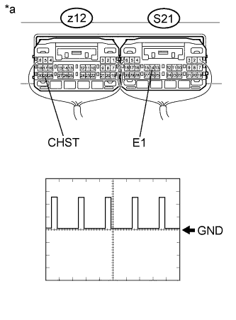
Text in Illustration *a Component with harness connected
(Plugin Charge Control ECU Assembly)
Measure the waveform.
Item Contents Tester Connection z12-29 (CHST) - S21-14 (E1) Equipment Setting 5 V/DIV., 50 ms/DIV. Condition Power switch on (IG) Tech Tips
The waveform output from terminal CHST can be measured without connecting the electric vehicle charger cable assembly by turning the power switch on (IG).
-
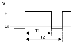
Text in Illustration *a Reference diagram for duty calculation Calculate duty (%) based on the CHST waveform.
Tech Tips
Calculate duty (%) using the following formula: Duty (%) = T1 / T2 x 100 (%)
-
Compare the Data List item "Charger State Pulse Duty Ratio" with the duty (%) calculated based on CHST waveform.
Result Result Proceed to The difference between "Charger State Pulse Duty Ratio" and the duty (%) calculated based on CHST waveform is less than 20 %. A The difference between "Charger State Pulse Duty Ratio" and the duty (%) calculated based on CHST waveform is 20 % or more. B -
Turn the power switch off.
B
REPLACE PLUGIN CHARGE CONTROL ECU ASSEMBLY Click here
A 
REPLACE ELECTRIC VEHICLE CHARGER ASSEMBLY Click here
-