PLUG-IN CHARGE CONTROL SYSTEM, Diagnostic DTC:P0D81-643
| DTC Code | DTC Name |
|---|---|
| P0D81-643 | Input AC Voltage Malfunction |
DESCRIPTION
Refer to the description for DTC P0D3E-234 Click here.
| DTC No. | INF Code | DTC Detection Condition | Trouble Area |
|---|---|---|---|
| P0D81 | 643 | VAC sensor voltage is out of the specified range (too high or too low). (1 trip detection logic) |
|
| DTC No. | INF Code | Data List |
|---|---|---|
| P0D81 | 643 |
|
WIRING DIAGRAM
Refer to the wiring diagram for DTC P0D3F-235 Click here.
INSPECTION PROCEDURE
Tech Tips
After the repair, check that the Data List item "State of Charge (All Bat)" is 70% or less, then plug-in charge the vehicle for 1 minute or more and check that DTCs are not output.
PROCEDURE
-
CHECK DTC OUTPUT (PLUG-IN CONTROL)
-
Connect the GTS to the DLC3.
-
Turn the power switch on (IG).
-
Enter the following menus: Powertrain / Plug-in Control / Trouble Codes.
-
Check if DTCs are output.
Result Result Proceed to Only P0D81-643 is output or P0D81-643 and DTCs other than the ones in the table below are also output. A Any of the following DTCs are also output. B DTC No. Relevant Diagnosis P0D3E-234 On-Board Charger Input AC Voltage Sensor Range / Performance P0D3F-235 On-Board Charger Input AC Voltage Sensor Circuit Low P0D40-236 On-Board Charger Input AC Voltage Sensor Circuit High Tech Tips
P0D81-643 may be output due to a malfunction which causes the DTCs in the table above to be output. In this case, first troubleshoot the output DTCs in the table above. Then, perform a reproduction test to check that no DTCs are output.
-
Turn the power switch off.
B 
GO TO DTC CHART (PLUG-IN CHARGE CONTROL SYSTEM) Click here
A 
-
-
CHECK PLUG-IN CHARGE STATE
Tech Tips
-
Check with the customer if the 220 to 240 V power used for plug-in charging was supplied by a power company.
-
If the electric vehicle charger cable assembly that was used to plug-in charge the vehicle is available, perform a reproduction test using it and a known good socket as follows. This allows the electric vehicle charger cable assembly to be determined as OK or NG when the vehicle is not malfunctioning.
-
Plug-in charge the vehicle using a known good socket.
-
Connect the Techstream to the DLC3.
-
Turn the power switch on (IG).
-
Clear DTC.
-
Enter the following menus: Powertrain / Plug-in Control / Data List.
-
Check that "State of Charge (All Bat)" shows 70% or less.
-
Turn the power switch off.
-
Connect the electric vehicle charger cable assembly and fully charge the vehicle. Check that plug-in charge control system DTCs are not output.
Note
Use the same 220 to 240 V power that the customer used to plug-in charge the vehicle when the DTC was stored, if possible.
Result Result Proceed to DTCs are output or plug-in charge cannot be completed. A DTCs are not output and plug-in charge has been completed. B Tech Tips
-
If the AC input voltage is too low or too high after connecting the electric vehicle charger cable assembly to the external outlet (before starting plug-in charge), this DTC is output.
-
Whether a malfunction indicated by this DTC exists in the vehicle or in other parts can be determined by comparing the following value. (Use the same AC supply voltage that the customer used to plug-in charge the vehicle, if possible.)
-
Freeze frame data item "On-Board Charger Input Voltage" (voltage when the malfunction occurred).
-
Data list item "On-Board Charger Input Voltage" after the vehicle has been plug-in charged using a known good socket.
-
-
B
END (NO MALFUNCTION VEHICLE)
A
-
-
CHECK PLUGIN CHARGE CONTROL ECU ASSEMBLY (VAC SENSOR VOLTAGE)
Tech Tips
AC voltage input to the vehicle is supplied a few seconds after starting plug-in charging. If DTC P0D81-643 is stored, AC input voltage will be cut off within a few seconds. Prepare for measurement before starting plug-in charging.
-
Connect the GTS to the DLC3.
-
Turn on the remote climate control system.
Tech Tips
For the list of operating conditions of the remote climate control system Click here.
-
Enter the following menus: Powertrain / Plug-in Control / Data List
-
Select "On-Board Charger Input Voltage" in the Data List.
Tester Display Measurement Item/Range On-Board Charger Input Voltage Effective AC voltage (VAC sensor value) input to the electric vehicle charger assembly from the charging inlet/
Min.: 0.0 V, Max.: 6553.5 V
-
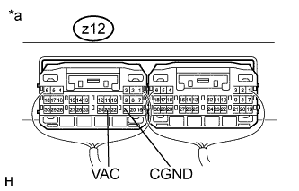
Text in Illustration *a Component with harness connected
(Plugin Charge Control ECU Assembly)
Set the tester to measure the following terminals.
Item Content Terminal z12-23 (VAC) - z12-21 (CGND) Tester Setting AC Voltage Range -
Start plug-in charging and compare the Data List item "On-Board Charger Input Voltage" with the following value: actual measurement of VAC terminal voltage x 1000/7.
Result Result Proceed to The difference between "On-Board Charger Input Voltage" and "actual measured voltage of VAC terminal x 1000/7" is less than 60 V A The difference between "On-Board Charger Input Voltage" and "actual measured voltage of VAC terminal x 1000/7" is 60 V or more B -
Turn the power switch off.
-
Stop plug-in charging the vehicle.
B
REPLACE PLUGIN CHARGE CONTROL ECU ASSEMBLY Click here
A 
REPLACE ELECTRIC VEHICLE CHARGER ASSEMBLY Click here
-