PLUG-IN CHARGE CONTROL SYSTEM, Diagnostic DTC:P0D67-844
| DTC Code | DTC Name |
|---|---|
| P0D67-844 | On-Board Charger Malfunction |
DESCRIPTION
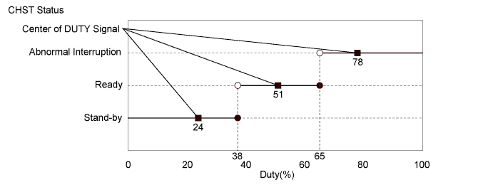
The electric vehicle charger assembly sends the status of the electric vehicle charger assembly to the plugin charge control ECU assembly as a CHST signal (charger operation status signal).
The status of the CHST signal (charger operation status signal) has 3 patterns: stand-by, ready and abnormal interruption. The stand-by state indicates that the on-board charger is "on" and the electric vehicle charger assembly has started correctly. The ready state indicates that AC input power source voltage is received correctly and both the CHRQ signal (charging request signal) and CHEN signal (electric vehicle charger gate open/close request signal) have turned on. The abnormal interruption state indicates that an internal malfunction of the electric vehicle charger assembly or overheating is occurring in the electric vehicle charger assembly.
The electric vehicle charger assembly has self-protection functions. If a malfunction occurs, it sends the CHST signal (charger operation status signal) to the plugin charge control ECU assembly to cancel charging. The electric vehicle charger assembly also limits its output if overheating occurs while charging or cancels charging when an internal malfunction occurs.
| DTC No. | INF Code | DTC Detection Condition | Trouble Area |
|---|---|---|---|
| P0D67 | 844 | A signal, indicating self-diagnosis malfunction, from the electric vehicle charger assembly is received. (1 trip detection logic) |
|
| DTC No. | INF Code | Data List |
|---|---|---|
| P0D67 | 844 |
|
WIRING DIAGRAM
Refer to the wiring diagram for DTC P316C-846 Click here.
INSPECTION PROCEDURE
Tech Tips
After the repair, check that the Data List item "State of Charge (All Bat)" is 70% or less, then plug-in charge the vehicle until it completes and check that DTCs are not output.
PROCEDURE
-
CHECK DTC OUTPUT (HYBRID CONTROL)
-
Connect the GTS to the DLC3.
-
Turn the power switch on (IG).
-
Enter the following menus: Powertrain / Hybrid Control / Trouble Codes.
-
Check if DTCs are output.
Result Result Proceed to Only P0D67-844 is output or P0D67-844 and DTCs other than the ones in the table below are also output. A Any of the following DTCs are also output. B DTC No. Relevant Diagnosis P0A1D-144, 148, 162, 721, 722, 723, 787, 818, 821, 823 Hybrid Powertrain Control Module P0ADC-226 Hybrid Battery Positive Contactor Control Circuit High P0AE0-228 Hybrid Battery Negative Contactor Control Circuit High P2511-149 HV CPU Power Relay Sense Circuit Intermittent No Continuity P3004-131, 803 Power Cable Malfunction U019B-440 Lost Communication with Battery Charger Control Module Tech Tips
P0D67-844 may be output due to a malfunction which causes the DTCs in the table above to be output. In this case, first troubleshoot the output DTCs in the table above. Then, perform a reproduction test to check that no DTCs are output.
-
Turn the power switch off.
B 
GO TO DTC CHART (HYBRID CONTROL SYSTEM) Click here
A 
-
-
CHECK DTC OUTPUT (PLUG-IN CONTROL)
-
Connect the GTS to the DLC3.
-
Turn the power switch on (IG).
-
Enter the following menus: Powertrain / Plug-in Control / Trouble Codes.
-
Check if DTCs are output.
Result Result Proceed to Only P0D67-844 is output or P0D67-844 and DTCs other than the ones in the table below are also output. A Any of the following DTCs are also output. B DTC No. Relevant Diagnosis P0D20-422 Charger Relay Stuck Open P0D4D-404 On-Board Charger Output Voltage Sensor Circuit Range / Performance P2511-441 Reset Detected P321D-644 Charging System Voltage High U0293-439, 449 Lost Communication with Hybrid Powertrain Control Module Tech Tips
P0D67-844 may be output due to a malfunction which causes the DTCs in the table above to be output. In this case, first troubleshoot the output DTCs in the table above. Then, perform a reproduction test to check that no DTCs are output.
-
Turn the power switch off.
B
GO TO DTC CHART (PLUG-IN CHARGE CONTROL SYSTEM) Click here
A
-
-
CHECK PLUG-IN CHARGE STATE
Tech Tips
-
Check with the customer if the 220 to 240 V power used for plug-in charging was supplied by a power company.
-
If the electric vehicle charger cable assembly that was used to plug-in charge the vehicle is available, perform a reproduction test using it and a known good socket as follows. This allows the electric vehicle charger cable assembly to be determined as OK or NG when the vehicle is not malfunctioning.
-
Plug-in charge the vehicle using a known good socket.
-
Connect the GTS to the DLC3.
-
Turn the power switch on (IG).
-
Clear DTC.
-
Enter the following menus: Powertrain / Plug-in Control / Data List.
-
Check that "State of Charge (All Bat)" shows 70% or less.
-
Turn the power switch off.
-
Connect the electric vehicle charger cable assembly and fully charge the vehicle. Check that plug-in charge control system DTCs are not output.
Note
Use the same 220 to 240 V power that the customer used to plug-in charge the vehicle when the DTC was stored, if possible.
Result Result Proceed to DTCs are output or plug-in charge cannot be completed. A DTCs are not output and plug-in charge has been completed. B Tech Tips
-
This DTC could be output due to rapid fluctuation of AC input voltage.
-
As the voltage fluctuates quickly, it is difficult to check the plug-in charge state by reading the freeze frame data or Data List item "On-Board Charger Input Voltage".
-
-
B
END (NO MALFUNCTION VEHICLE)
A
-
-
CHECK PLUGIN CHARGE CONTROL ECU ASSEMBLY (CHECK WAVEFORM (CHST))
Tech Tips
The following procedure is used to check for a malfunction in an internal circuit of the plugin charge control ECU assembly.
-
Connect the GTS to the DLC3.
-
Connect an oscilloscope between the plugin charge control ECU assembly terminals specified in the table below.
-
Turn the power switch on (IG).
-
Enter the following menus: Powertrain / Plug-in Control / Data List
-
Select "Charger State Pulse Duty Ratio" in the Data List.
Tester Display Measurement Item/Range Charger State Pulse Duty Ratio Electric vehicle charger assembly charging status indicated by duty/
Min.: 0.0 %, Max.: 100.0 %
-
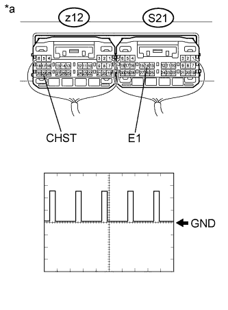
Text in Illustration *a Component with harness connected
(Plugin Charge Control ECU Assembly)
Measure the waveform.
Item Contents Tester Connection z12-29 (CHST) - S21-14 (E1) Equipment Setting 5 V/DIV., 50 ms/DIV. Condition Power switch on (IG) Tech Tips
The waveform output from terminal CHST can be measured without connecting the electric vehicle charger cable assembly by turning the power switch on (IG).
-
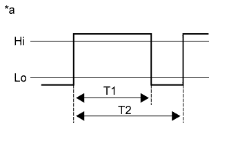
Text in Illustration *a Reference diagram for duty calculation Calculate duty (%) based on the CHST waveform.
Tech Tips
Calculate duty (%) using the following formula: Duty (%) = T1 / T2 x 100 (%)
-
Compare the Data List item "Charger State Pulse Duty Ratio" with the duty (%) calculated based on CHST waveform.
Result Result Proceed to The difference between "Charger State Pulse Duty Ratio" and the duty (%) calculated based on CHST waveform is less than 20 %. A The difference between "Charger State Pulse Duty Ratio" and the duty (%) calculated based on CHST waveform is 20 % or more. B -
Turn the power switch off.
B
REPLACE PLUGIN CHARGE CONTROL ECU ASSEMBLY Click here
A 
REPLACE ELECTRIC VEHICLE CHARGER ASSEMBLY Click here
-