CHARGE INDICATOR INSPECTION
-
INSPECT INDICATOR LAMP ASSEMBLY
-
Check that the switch illuminates.
-
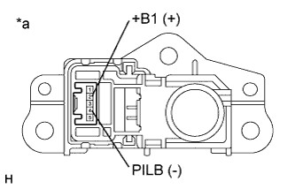
Apply auxiliary battery voltage between the terminals of the switch, and check the illumination condition of the indicator lamp assembly.
OK Tester Connection Switch Condition Specified Condition 2 (+B1) - 4 (PILB) Auxiliary battery positive (+) → Terminal 2 (+B1) Auxiliary battery negative (-) → Terminal 4 (PILB) Charging indicator illuminates Auxiliary battery voltage is not applied between terminals 2 (+B1) and 4 (PILB) Charging indicator not illuminates Text in Illustration *a Component without harness connected
(Indicator Lamp Assembly)
-
-
Check the operation of the courtesy switch.
-
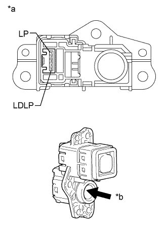
Text in Illustration *a Component without harness connected
(Indicator Lamp Assembly)
*b Push Using a screwdriver with its tip wrapped with protective tape, operate the switch and measure the resistance.
Standard Resistance Tester Connection Switch Condition Specified Condition 1 (LP) - 5 (LDLP) Not pushed Below 1 Ω Pushed 10 kΩ or higher
-
-