CHARGE CABLE INSPECTION
-
INSPECT ELECTRIC VEHICLE CHARGER CABLE ASSEMBLY
-
Visual inspection *A
-
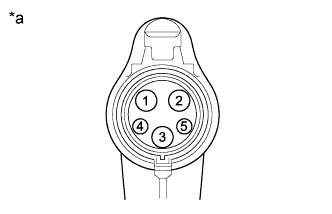
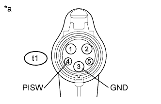
Text in Illustration *a Electric Vehicle Charger Cable Assembly
(Charging Connector Side)
Check if any foreign matter is attached to the connecting part of the electric vehicle charger cable assembly.
-
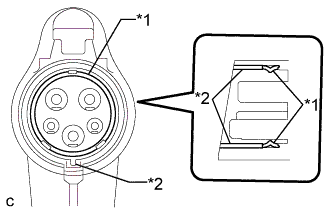
Text in Illustration *1 EV Charge Connector Seal *2 EV Charge Connector Retainer Check the installation condition of the EV charge connector seal (w/ EV Charge Connector Seal).
OK The EV charge connector seal is installed securely and not twisted or moved out of place. Note
If the EV charge connector seal is loose, remove the EV charge connector seal.
-
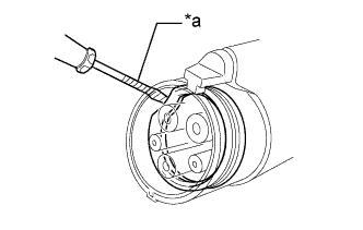
Text in Illustration *a Protective Tape Using a screwdriver, remove the EV charge connector seal from the electric vehicle charger cable assembly.
Note
The water tightness of the electric vehicle charger cable (charging inlet side) and insulation performance of the electric vehicle charger cable assembly are ensured without the EV charge connector seal installed. It is not necessary to reinstall the EV charge connector seal.
Tech Tips
-
The EV charge connector seal can be removed without removing the EV charge connector retainer.
-
Tape the screwdriver tip before use.
-
-
-
Check the latch release button (PISW)
-
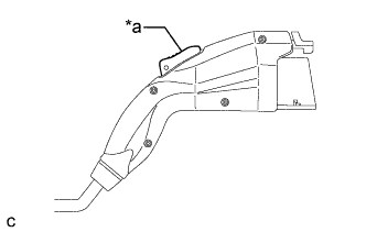
Text in Illustration *a Latch Release Button (PISW) Check that the latch release button (PISW) can be pressed with no abnormal resistance.
-
-
Check connection
-
Check that the electric vehicle charger cable assembly and electric vehicle charger cable (charging inlet side) can be connected smoothly.
OK The electric vehicle charger cable assembly and electric vehicle charger cable (charging inlet side) connect smoothly. If the result is not as specified, perform the visual inspection *A as well as the following checks.
-
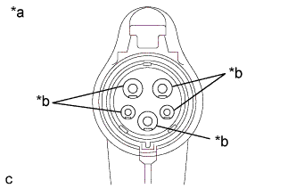
Text in Illustration *a Electric Vehicle Charger Cable Assembly
(Charging Connector Side)
*b Terminal Check that the terminals of the electric vehicle charger cable assembly (charging connector side) are not bent or deformed.
OK The terminals are not bent or deformed. If the result is not as specified, replace the electric vehicle charger cable assembly.
-
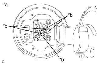
Text in Illustration *a Electric Vehicle Charger Cable
(Charging Inlet Side)
*b Terminal Check that the terminals of the electric vehicle charger cable (charging inlet side) are not bent or deformed.
OK The terminals are not bent or deformed. If the result is not as specified, replace the electric vehicle charger cable.
Tech Tips
If the electric vehicle charger cable assembly (charging connector side) is connected to the electric vehicle charger cable (charging inlet side) incorrectly, the terminals may be bent or deformed.
-
-
Check operation
-
Perform charge cable On-vehicle Inspection Click here.
-
-
Check for short
CAUTION:
Wear insulated gloves.
-
Plug in the electric vehicle charger cable assembly to a socket.
Tech Tips
Make sure not to connect electric vehicle charger cable assembly to the vehicle side charging inlet.
-
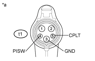
Text in Illustration *a Electric Vehicle Charger Cable Assembly
(Charging Connector Side)
Measure the voltage according to the value(s) in the table below.
Standard Voltage Tester Connection Condition Specified Condition t1-4 (PISW) - t1-3 (GND) Latch release button (PISW) pressed Below 1 V t1-5 (CPLT) - t1-3 (GND) Latch release button (PISW) not pressed Below 1 V t1-5 (CPLT) - t1-3 (GND)
-
Power indicator illuminated
-
Error warning indicator not illuminated
11.4 to 12.6 V -
-
Disconnect the electric vehicle charger cable assembly from the socket.
-
-
Check manual electricity leakage test operation
-
Plug in the electric vehicle charger cable assembly to a socket.
Tech Tips
-
Make sure not to connect the electric vehicle charger cable assembly to the vehicle side charging inlet.
-
Plug-in charging is not performed while the manual electricity leakage test is operating (while the error warning indicator is illuminated).
-
-
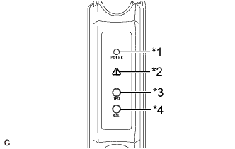
Text in Illustration *1 Power Indicator *2 Error Warning Indicator *3 Test Button *4 Reset Button Check the condition of the lamps according to the following table.
Standard Inspection Item Condition Specified Condition Power Indicator Condition Error Warning Indicator Condition Manual electricity leakage test operation Test button pressed
(once)
Flashes
(3 times)
Illuminated Reset operation Reset button pressed
(once)
Illuminated Off Tech Tips
-
Press and hold test or reset button for approximately 1 second.
-
Pressing the Reset button or disconnecting and reconnecting the electric vehicle charger cable assembly to the socket resets the operation of the manual electricity leakage test.
-
-
Disconnect the electric vehicle charger cable assembly from the socket.
-
-
Check for open
-
Text in Illustration *a Electric Vehicle Charger Cable Assembly
(Charging Connector Side)
Measure the resistance according to the value(s) in the table below.
Standard Resistance Tester Connection Condition Specified Condition t1-4 (PISW) - t1-3 (GND) Latch release button (PISW) pressed 430 to 530 Ω t1-4 (PISW) - t1-3 (GND) Latch release button (PISW) not pressed 135 to 165 Ω
-
-