HV BATTERY REMOVAL
-
PRECAUTION
CAUTION:
-
The hybrid system has high-voltage circuits. Accidents, such as electric shock, or electric leaks may result if the hybrid system is not operated in a correct manner. Make sure to follow the correct procedure Click here.
-
When disposing of HV batteries and hybrid vehicle supply stack assemblies, make sure to return them through an authorized collection agent who is capable of handling them safely.
-
Before returning the HV battery, make sure to perform a recovery inspection Click here.
-
Before returning the hybrid vehicle supply stack sub-assembly, make sure to perform a recovery inspection Click here.
-
Make a note of the output DTCs as some of them may be necessary for "Recovery Inspection" of the HV battery and hybrid vehicle supply stack sub-assembly.
-
-
READ VALUE USING GTS
-
Connect the GTS to the DLC3.
-
Turn the power switch on (IG).
-
Enter the following menus: Powertrain / Hybrid Control / Data List / Temp of Batt TB 1 - 12.
-
Read the Data List.
Note
If any of the temperatures listed in "Temp of Batt TB1 - 12" are 50°C or more, leave the vehicle until the temperature drops to less than 50°C.
-
-
CHECK FOR DTCS
-
Check for DTCs Click here
Note
Confirm that DTC P0AA6 (Hybrid Battery Voltage System Isolation Fault) is not output before doing removal or installation work inside the battery. If this DTC is output, perform troubleshooting for this DTC first.
-
-
REMOVE SERVICE PLUG GRIP
-
REMOVE INVERTER COVER
CAUTION:
Wear insulated gloves.
-
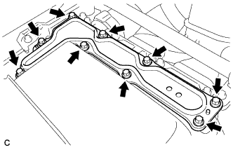
Remove the 9 bolts and inverter cover.
Note
Make sure to pull the inverter cover straight up, as a connector is connected to the bottom of the cover.
-
-
CHECK TERMINAL VOLTAGE
CAUTION:
Wear insulated gloves.
Note
Do not allow any foreign matter or water to enter the inverter with converter assembly.
-
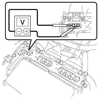
Using a voltmeter, measure the voltage between the terminals of the 2 phase connectors.
Standard voltage 0 V Tech Tips
Use measuring range of DC 750 V or more on the voltmeter.
-
-
INSTALL INVERTER COVER
CAUTION:
Wear insulated gloves.
-
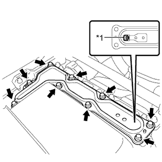
Text in Illustration *1 Interlock Install the inverter cover with the 9 bolts to the inverter with converter assembly.
- Torque:
- 11 N*m { 112 kgf*cm, 8 ft.*lbf }
Note
-
Make sure that the interlock is fully engaged.
-
Do not allow any foreign matter or water to enter the inverter with converter assembly.
-
-
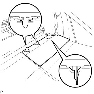
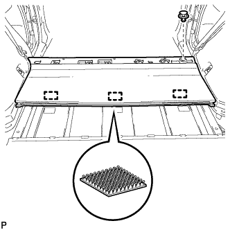
REMOVE REAR NO. 2 FLOOR BOARD
-
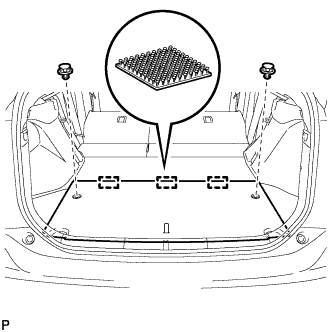
Using a clip remover, remove the 2 clips.
-
Disengage the 3 fasteners and remove the rear No. 2 floor board.
-
-
REMOVE REAR NO. 4 FLOOR BOARD SUB-ASSEMBLY
-
Remove the rear No.4 floor board sub-assembly.
-
-
REMOVE DECK FLOOR BOX LH
Tech Tips
Use the same procedure as for the RH side Click here.
-
REMOVE TONNEAU COVER ASSEMBLY
-
Remove the tonneau cover assembly.
-
-
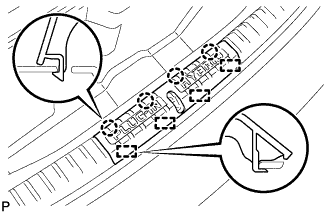
REMOVE REAR NO. 2 FLOOR BOARD SUB-ASSEMBLY
-
Disengage the claw and 2 clips, and remove the rear No. 2 floor board sub-assembly.
-
-
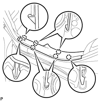
REMOVE REAR NO. 1 FLOOR BOARD SUB-ASSEMBLY
-
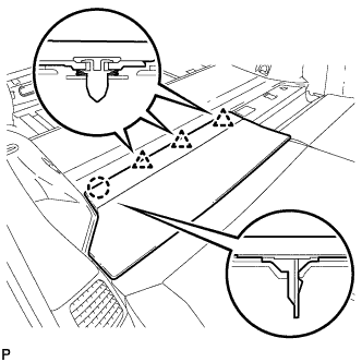
Disengage the claw and 3 clips, and remove the rear No. 1 floor board sub-assembly.
-
-
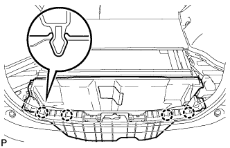
REMOVE REAR NO. 1 FLOOR BOARD
-
Fold the rear seatback assembly LH forward.
-
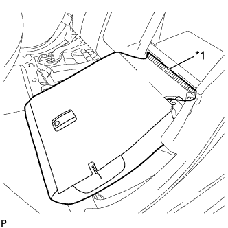
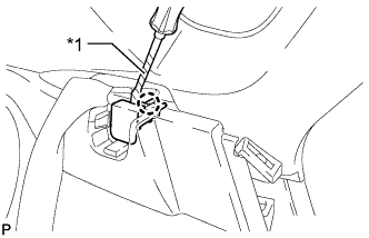
Text in Illustration *1 Fastener Disengage the fastener.
-
Fold the rear seatback assembly LH forward.
-
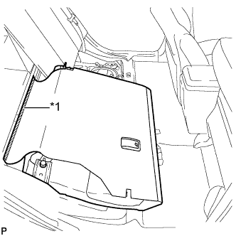
Text in Illustration *1 Fastener Disengage the fastener.
-
Using a clip remover, remove the clip.
-
Disengage the 3 fasteners and remove the rear No. 1 floor board.
-
-
REMOVE DECK TRIM SERVICE HOLE COVER
-
Disengage the 4 claws.
-
Disengage the 4 guides and remove the deck trim service hole cover.
-
-
REMOVE REAR DECK TRIM COVER
-
Disengage the 4 claws and remove the rear deck trim cover.
-
-
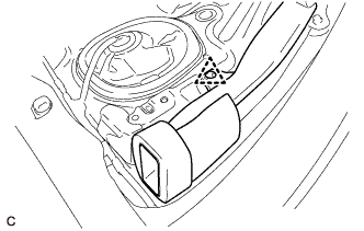
REMOVE REAR DOOR SCUFF PLATE LH
-
Disengage the 7 claws and remove the rear door scuff plate LH.
-
-
REMOVE REAR DOOR OPENING TRIM WEATHERSTRIP LH
-
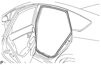
Remove the rear door opening trim weatherstrip LH.
-
-
REMOVE REAR DOOR SCUFF PLATE RH
Tech Tips
Use the same procedure described for the LH side.
-
REMOVE REAR DOOR OPENING TRIM WEATHERSTRIP RH
Tech Tips
Use the same procedure described for the LH side.
-
REMOVE REAR SEAT CUSHION ASSEMBLY
-
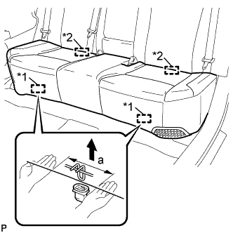
Text in Illustration *1 Front Hook *2 Rear Hook Disengage the front hook of the rear seat cushion assembly from the vehicle body as shown in the illustration.
Standard Measurement Dimension Measurement a 100 mm (3.94 in.) or less Note
Follow the instructions below carefully as the cushion frame can be deformed easily.
-
Choose a front hook to disengage first. Place your hands near the front hook as shown in the illustration. Then lift the seat cushion to disengage the front hook.
-
Repeat the above procedure for the other hook.
-
-
Disengage the 2 rear hooks of the rear seat cushion assembly from the rear seatback assembly.
-
Remove the rear seat cushion assembly.
Note
Be careful not to damage the vehicle body.
-
-
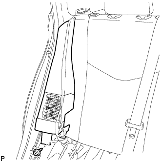
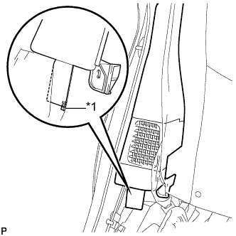
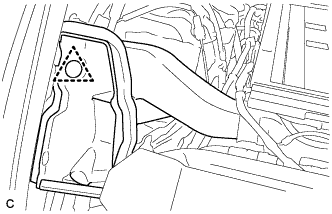
REMOVE REAR SIDE SEATBACK ASSEMBLY LH
-
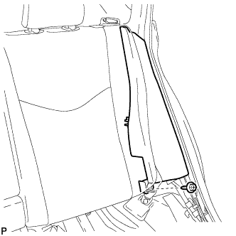
Remove the bolt.
-
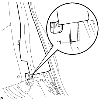
Text in Illustration *1 Fastener Disengage the fastener.
-
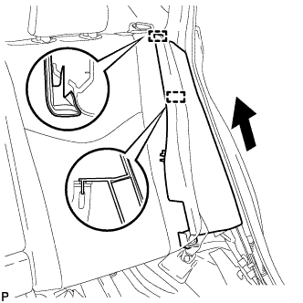
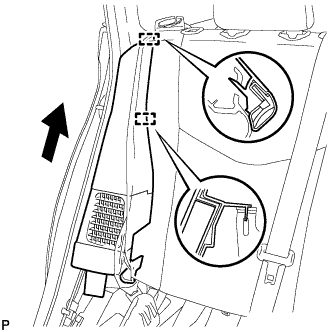
Disengage the 2 guides and remove the rear side seatback assembly LH as shown in the illustration.
-
-
REMOVE REAR SIDE SEATBACK ASSEMBLY RH
-
Remove the bolt.
-
Text in Illustration *1 Fastener Disengage the fastener.
-
Disengage the 2 guides and remove the rear side seatback assembly RH as shown in the illustration.
-
-
REMOVE LUGGAGE HOLD BELT STRIKER ASSEMBLY (for LH Side)
-
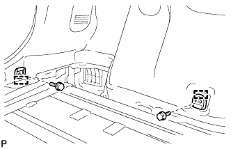
Remove the 2 bolts.
-
Disengage each guide and remove the 2 luggage hold belt striker assemblies.
-
-
REMOVE TONNEAU COVER HOLDER CAP (for LH Side)
-
Text in Illustration *1 Protective Tape Using a screwdriver, disengage the claw and remove the tonneau cover holder cap.
Tech Tips
Tape the screwdriver tip before use.
-
-
REMOVE LUGGAGE HOLD BELT STRIKER ASSEMBLY (for RH Side)
Tech Tips
Use the same procedure described for the LH side.
-
REMOVE TONNEAU COVER HOLDER CAP (for RH Side)
Tech Tips
Use the same procedure described for the LH side.
-
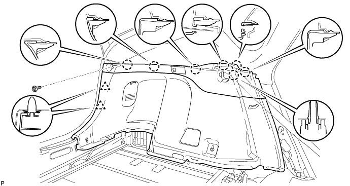
REMOVE DECK TRIM SIDE PANEL ASSEMBLY LH
-
Remove the screw.
-
Disengage the 7 claws and 2 clips.
-
Disconnect the connector and remove the deck trim side panel assembly LH.
-
-
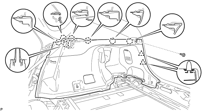
REMOVE DECK TRIM SIDE PANEL ASSEMBLY RH
-
Remove the screw.
-
Disengage the 7 claws and 2 clips, and remove the deck trim side panel assembly RH.
-
-
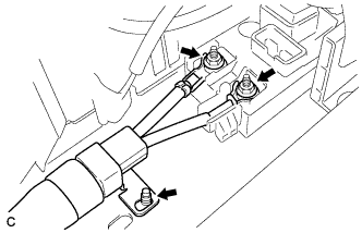
REMOVE BATTERY COOLING BLOWER ASSEMBLY (for RH Side)
Note
-
Be sure not to touch the fan part of the battery cooling blower assembly.
-
Do not lift the battery cooling blower assembly using the wire harness.
-
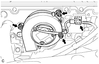
Disconnect the connector and clamp from the battery cooling blower assembly.
-
Remove the 3 nuts and battery cooling blower assembly (for RH side).
-
-
REMOVE BATTERY COOLING BLOWER ASSEMBLY (for LH Side)
Note
-
Be sure not to touch the fan part of the battery cooling blower assembly.
-
Do not lift the battery cooling blower assembly using the wire harness.
-
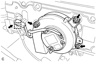
Disconnect the connector and clamp from the battery cooling blower assembly.
-
Remove the 3 nuts and battery cooling blower assembly (for LH side).
-
-
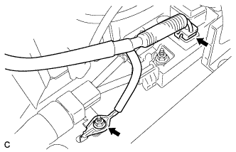
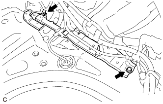
REMOVE HYBRID BATTERY HOSE ASSEMBLY
-
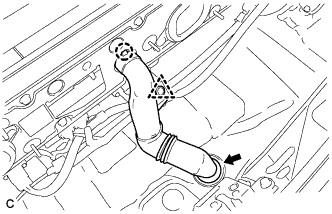
Disconnect the clip.
-
Disengage the claw.
-
Disconnect the grommet and remove the hybrid battery hose assembly.
-
-
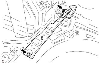
REMOVE NO. 4 HYBRID VEHICLE BATTERY CARRIER BRACKET
-
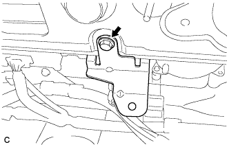
Remove the bolt and No. 4 hybrid vehicle battery carrier bracket.
-
-
REMOVE NO. 2 HYBRID VEHICLE BATTERY SHIELD PANEL
CAUTION:
Wear insulated gloves.
-
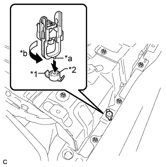
Text in Illustration *1 Battery Cover Lock Striker *2 Button *a Projection *b Turn Using the service plug grip, remove the battery cover lock striker.
Tech Tips
Insert the projection part of the service plug grip, and turn the button of the battery cover lock striker counterclockwise, and release the lock.
-
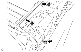
Remove the 3 nuts and No. 2 hybrid vehicle battery shield panel.
-
-
REMOVE NO. 1 HYBRID VEHICLE BATTERY SHIELD PANEL
CAUTION:
Wear insulated gloves.
-
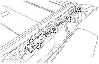
Disengage the 2 claws and remove the 3 clamps and electrical key oscillator.
-
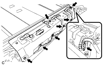
Disconnect the connector and clamp.
-
Remove the 7 nuts and No. 1 hybrid vehicle battery shield panel.
-
-
DISCONNECT EV CHARGER WIRE
CAUTION:
Wear insulated gloves.
-
Disconnect the connector.
Note
Insulate the disconnected connector with insulating tape.
-
Remove the nut and disconnect the electric vehicle charger wire.
-
-
DISCONNECT FRAME WIRE
CAUTION:
Wear insulated gloves.
-
Using an insulated tool, remove the 2 nuts.
-
Disconnect the shield wire ground and frame wire.
Note
Insulate the disconnected terminal with insulating tape.
-
-
REMOVE NO. 1 HYBRID BATTERY INTAKE DUCT
-
Remove the clip and No. 1 hybrid battery intake duct.
-
-
REMOVE NO. 2 HYBRID BATTERY INTAKE DUCT
-
Remove the clip and No. 2 hybrid battery intake duct.
-
-
REMOVE HV BATTERY
CAUTION:
Wear insulated gloves.
Note
-
Insulate the removed connectors and terminals with insulating tape.
-
Use cardboard or other similar material to protect the HV battery and vehicle body from damage.
-
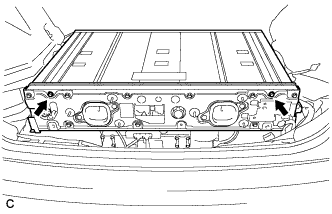
Remove the 2 bolts from each upper back door damper stay bracket.
Tech Tips
Have an assistant support the back door.
-
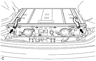
Rotate each upper back door damper stay bracket upside-down as shown in the illustration and install them with the 2 bolts.
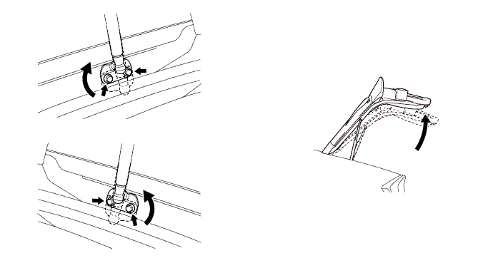
Tech Tips
Make sure to provide enough clearance so that the vehicle body will not be damaged during removal/installation of the HV battery.
-
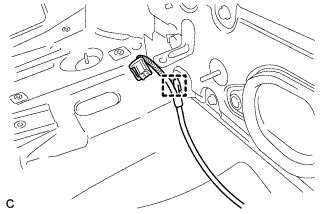
Disconnect the clamp.
-
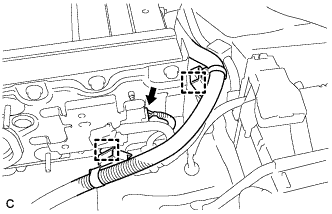
Disconnect the connector and 2 clamps.
-
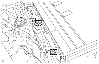
Disconnect the 4 clamps.
-
Remove the 2 bolts.
-
Install the 2 engine hangers (12281-28010) with the 2 bolts as shown in the illustration.
- Torque:
- 22 N*m { 224 kgf*cm, 16 ft.*lbf }
-
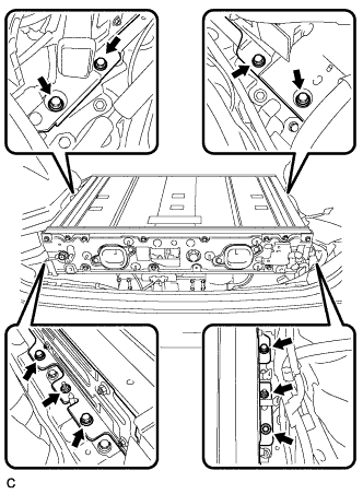
Remove the 8 bolts and 2 nuts.
-
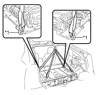
Text in Illustration *1 Hook Set the hooks and straps as shown in the illustration.
-
Using a suitable adaptor such as straps, remove the HV battery.
CAUTION:
To prevent any accidents and injuries due to the weight of the HV battery, follow all specified procedures and be careful to balance the HV battery when removing or installing it.
Note
Make sure that the HV battery does not interfere with the vehicle body during removal or installation.
-
-
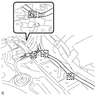
REMOVE ELECTRIC VEHICLE CHARGER ASSEMBLY
CAUTION:
Wear insulated gloves.
-
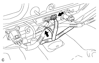
Disconnect the 2 connectors.
-
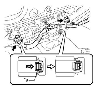
Text in Illustration *a Green-colored Lock Disconnect the clamp.
-
Using a screwdriver, slide the 2 green-colored locks of the 2 connectors in the direction indicated by the arrow in the illustration to release them and disconnect the 2 connectors.
Note
Insulate the removed connectors and terminals and connector with insulating tape.
-
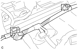
Disconnect the 2 clamps.
-
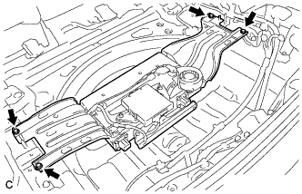
Remove the 4 bolts and electric vehicle charger assembly.
-
Remove the 4 bolts and 2 electric vehicle charger brackets.
-
-
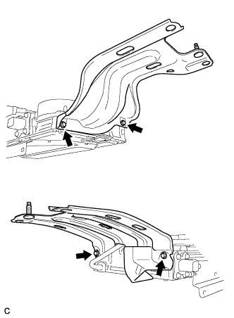
REMOVE CHILD RESTRAINT SEAT ANCHOR BRACKET SUB-ASSEMBLY RH
-
Disconnect the clamp.
-
Remove the 2 bolts and child restraint seat anchor bracket sub-assembly RH.
-
-
REMOVE CHILD RESTRAINT SEAT ANCHOR BRACKET SUB-ASSEMBLY LH
-
Remove the 2 bolts and child restraint seat anchor bracket sub-assembly LH.
-
-
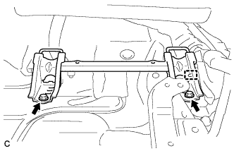
REMOVE NO. 2 HYBRID VEHICLE BATTERY MOUNT BRACKET
-
Disconnect the 4 clamps.
-
Remove the 2 bolts and No. 2 hybrid vehicle battery mount bracket.
-
-
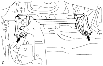
REMOVE NO. 1 HYBRID VEHICLE BATTERY MOUNT BRACKET
-
Remove the 2 bolts and No. 1 hybrid vehicle battery mount bracket.
-
-
PERFORM RECOVERY INSPECTION
-
Before returning the HV battery, make sure to perform a recovery inspection Click here.
-