PLUG-IN CHARGE CONTROL SYSTEM, Diagnostic DTC:P0560-117
| DTC Code | DTC Name |
|---|---|
| P0560-117 | System Voltage |
DESCRIPTION
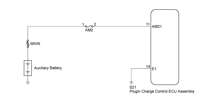
Battery power is constantly supplied to the back up power terminal of the plugin charge control ECU assembly to store DTCs and freeze frame data. Backup power is continually supplied after the power switch is turned off.
| DTC No. | INF Code | DTC Detection Condition | Trouble Area |
|---|---|---|---|
| P0560 | 117 |
|
|
WIRING DIAGRAM
INSPECTION PROCEDURE
Tech Tips
After the repair, turn the power switch off. Wait for 10 seconds or more, turn the power switch on (IG), and check that DTCs are not output.
PROCEDURE
-
CHECK HARNESS AND CONNECTOR (PLUGIN CHARGE CONTROL ECU ASSEMBLY - BODY GROUND)
-
Disconnect the S21 plugin charge control ECU assembly connector.
-
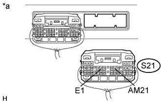
Text in Illustration *a Rear view of wire harness connector
(to Plugin Charge Control ECU Assembly)
Measure the voltage according to the value(s) in the table below.
Standard Voltage Tester Connection Condition Specified Condition S21-11 (AM21) - S21-14(E1) Power switch off 11 to 14 V S21-11 (AM21) - Body ground Power switch off 11 to 14 V -
Reconnect the S21 plugin charge control ECU assembly connector.
NG 
CHECK FUSE (AM2) Click here
OK 
-
-
CHECK AUXILIARY BATTERY
NG 
REPLACE AUXILIARY BATTERY Click here
OK 
REPLACE PLUGIN CHARGE CONTROL ECU ASSEMBLY Click here
-
CHECK FUSE (AM2)
-
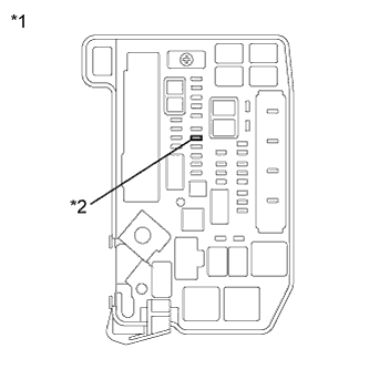
Text in Illustration *1 Engine Room Relay Block and Junction Block Assembly *2 AM2 Fuse Remove the AM2 fuse from the engine room relay block and junction block assembly.
-
Measure the resistance according to the value(s) in the table below.
Standard Resistance Tester Connection Condition Specified Condition AM2 fuse Always Below 1 Ω -
Install the AM2 fuse.
NG
REPLACE FUSE (AM2)
OK
-
-
CHECK HARNESS AND CONNECTOR (PLUGIN CHARGE CONTROL ECU ASSEMBLY - AM2 FUSE)
-
Text in Illustration *1 Engine Room Relay Block and Junction Block Assembly *2 AM2 Fuse Remove the AM2 fuse from the engine room relay block and junction block assembly.
-
Disconnect the S21 plugin charge control ECU assembly connector.
-
Measure the resistance according to the value(s) in the table below.
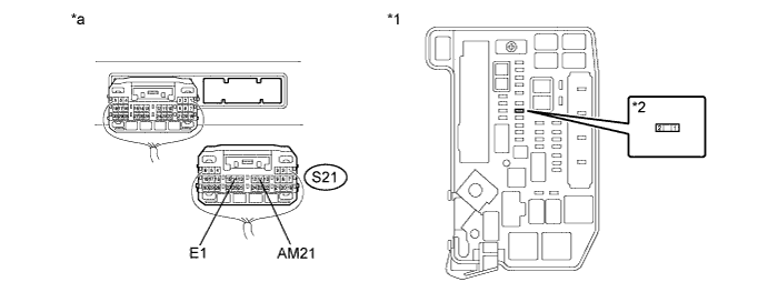
Text in Illustration *1 Engine Room Relay Block and Junction Block Assembly *2 AM2 Fuse *a Rear view of wire harness connector
(to Plugin Charge Control ECU Assembly)
- - Standard Resistance Tester Connection Condition Specified Condition S21-11 (AM21) - 2 (AM2 fuse) Power switch off Below 1 Ω S21-14 (E1) - Body ground Power switch off Below 1 Ω Tech Tips
Check that the ground point is securely installed.
-
Install the AM2 fuse.
-
Reconnect the S21 plugin charge control ECU assembly connector.
NG
REPAIR OR REPLACE HARNESS OR CONNECTOR
OK
CHECK POWER SOURCE CIRCUIT
-