PLUG-IN CHARGE CONTROL SYSTEM TERMINALS OF ECU
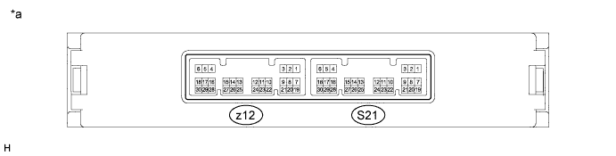
| *a | Component without harness connected (Plugin Charge Control ECU Assembly) |
- | - |
| Terminal No. (Symbol) |
Wiring Color | Terminal Description | Condition | Specified Condition |
|---|---|---|---|---|
| z12-18 (CHRQ) - S21-14 (E1) | - W-B | Electric vehicle charger assembly operation request signal | Plug-in charging | 7.5 to 8.5 V |
| Power switch on (IG), not plug-in charging | 0 to 1.5 V | |||
| z12-22 (ILMT) - S21-14 (E1) | - W-B | Electric vehicle charger assembly AC input current limit command signal | Plug-in charging | Pulse generation (Waveform 1) |
| z12-23 (VAC) - z12-21 (CGND) | - | Electric vehicle charger assembly AC input side voltage sensor | Power switch on (IG), electric vehicle charger cable assembly not connected | 4.83 to 6.16 V |
| z12-24 (ICHG) - z12-21 (CGND) | - | Electric vehicle charger assembly output side current sensor | Power switch on (IG), electric vehicle charger cable assembly not connected | 1.64 to 2.36 V |
| Plug-in charging | 1.64 to 7.0 V | |||
| z12-25 (VCHG) - z12-21 (CGND) | - | Electric vehicle charger assembly output side voltage sensor | Power switch on (IG), electric vehicle charger cable assembly not connected | 1.72 to 2.22 V |
| Plug-in charging | 1.72 to 6.0 V | |||
| z12-29 (CHST) - S21-14 (E1) | - W-B | Electric vehicle charger assembly operation status | Power switch on (IG) (charging stand-by) → Plug-in charging | Pulse generation (Waveform 2) |
| z12-30 (CHPW) - S21-14 (E1) | - W-B | Electric vehicle charger assembly output power command signal | Plug-in charging | Pulse generation (Waveform 3) |
| S21-2 (PISW) - S21-3 (CPG) | R - Y | Charging connector connection signal | Power switch on (IG), electric vehicle charger cable assembly not connected | 4.2 to 4.8 V |
| Power switch on (IG), electric vehicle charger cable assembly connected and latch release button (PI switch) pressed | 2.5 to 3.1 V | |||
| Power switch on (IG), electric vehicle charger cable assembly connected and latch release button (PI switch) not pressed | 1.2 to 1.8 V | |||
| S21-4 (CHRB) - S21-27 (E01) | SB - W-B | CHRB relay operation signal | Power switch on (IG), electric vehicle charger cable assembly not connected | 0 to 1.5 V |
| Plug-in charging | 10 to 14 V | |||
| S21-9 (PILB) - S21-14 (E1) | B - W-B | Charging indicator | Power switch on (IG), charging indicator turned off | 11 to 14 V |
| Charging, charging indicator illuminated | 1.5 to 4.5 V | |||
| S21-10 (IG2) - S21-14 (E1) | R - W-B | IG2 signal | Power switch on (IG) | 11 to 14 V |
| S21-11 (AM21) - S21-14 (E1) | SB - W-B | Constant power source | Power switch on (IG) | 11 to 14 V |
| S21-12 (CA4H) - S21-14 (E1) | L - W-B | CAN communication signal (Plug-in Bus) |
Power switch on (IG) | Pulse generation (Waveform 4) |
| S21-13 (CA4L) - S21-14 (E1) | W - W-B | CAN communication signal (Plug-in Bus) |
Power switch on (IG) | Pulse generation (Waveform 4) |
| S21-15 (CHRG) - S21-27 (E01) | P - W-B | CHRG relay operation signal | Power switch on (IG), electric vehicle charger cable assembly not connected | 0 to 1.5 V |
| Plug-in charging | 10 to 14 V | |||
| S21-16 (PTML) - S21-14 (E1) | G - W-B | Charging timer indicator | Charging timer function is set (Charging timer indicator illuminated) | 7 to 13 V |
| S21-17 (PTMS) - S21-14 (E1) | V - W-B | Charging timer switch status | Charging timer switch pressed | 0 to 1.5 V |
| Charging timer switch not pressed | 11 to 14 V | |||
| S21-21 (CPLT) - S21-3 (CPG) | G - Y | Charge voltage judgment and allowable amperage recognition signals | Plug-in charging | Pulse generation (Waveform 5) |
| S21-23 (+B1) - S21-14 (E1) | B - W-B | Charging power source | Power switch on (IG) | 11 to 14 V |
| S21-24 (MREL) - S21-14 (E1) | W - W-B | PIMR relay operation signal | Power switch on (IG) | 11 to 14 V |
| S21-25 (CA1H) - S21-14 (E1) | B - W-B | CAN communication signal (V1 Bus) |
Power switch on (IG) | Pulse generation (Waveform 6) |
| S21-26 (CA1L) - S21-14 (E1) | W - W-B | CAN communication signal (V1 Bus) |
Power switch on (IG) | Pulse generation (Waveform 6) |
| S21-29 (LDLP) - S21-14 (E1) | V - W-B | Charging port lid switch signal | Power switch on (IG), charging port lid open | 5 to 10 V |
-
Oscilloscope waveforms
Tech Tips
Oscilloscope waveform samples are provided here for informational purposes. Noise and fluttering waveforms have been omitted.
-
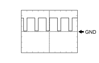
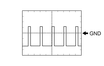
Waveform 1 (Electric vehicle charger assembly AC input current limit command signal)
Item Content Terminal z12-22 (ILMT) - S21-14 (E1) Equipment Setting 5 V/DIV., 50 ms/DIV. Condition Plug-in charging Tech Tips
Duty ratio varies by the AC input current limit value of the electric vehicle charger assembly.
-
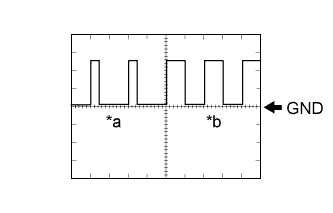
Text in Illustration *a Power switch on (IG) (charging stand-by) *b Plug-in charging Waveform 2 (Electric vehicle charger assembly operation status)
Item Content Terminal z12-29 (CHST) - S21-14 (E1) Equipment Setting 5 V/DIV., 50 ms/DIV. Condition Power switch on (IG) (charging stand-by) → Plug-in charging -
Waveform 3 (Electric vehicle charger assembly output power command signal)
Item Content Terminal z12-30 (CHPW) - S21-14 (E1) Equipment Setting 5 V/DIV., 50 ms/DIV. Condition Plug-in charging Tech Tips
Duty ratio varies by the output power command value of the electric vehicle charger assembly.
-
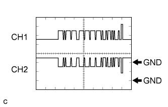
Waveform 4 (CAN communication signal (Plug-in Bus))
Item Content Terminal CH1: S21-12 (CA4H) - S21-14 (E1)
CH2: S21-13 (CA4L) - S21-14 (E1)
Equipment Setting 1 V/DIV., 50 μs/DIV. Condition Power switch on (IG) Tech Tips
The waveform will vary depending on the content of the digital communication (digital signal).
-
Waveform 5 (Charge voltage judgment and allowable amperage recognition signals)
Item Content Terminal S21-21 (CPLT) - S21-3 (CPG) Equipment Setting 5 V/DIV., 500 μs/DIV. Condition Plug-in charging Tech Tips
Duty ratio varies by the AC input allowable amperage of the charging cable and charging stand.
-
Waveform 6 (CAN communication signal (V1 Bus))
Item Content Terminal CH1: S21-25 (CA1H) - S21-14 (E1)
CH2: S21-26 (CA1L) - S21-14 (E1)
Equipment Setting 1 V/DIV., 50 μs/DIV. Condition Power switch on (IG) Tech Tips
The waveform will vary depending on the content of the digital communication (digital signal).
-