HYBRID BATTERY SYSTEM, Diagnostic DTC:P33A7-123, P33A8-123, P33AC-123, P33AD-123, P33AF-123
| DTC Code | DTC Name |
|---|---|
| P33A7-123 | Hybrid Battery Pack Air Temperature Sensor "C" Circuit Low |
| P33A8-123 | Hybrid Battery Pack Air Temperature Sensor "C" Circuit High |
| P33AC-123 | Hybrid Battery Pack Air Temperature Sensor "D" Circuit Low |
| P33AD-123 | Hybrid Battery Pack Air Temperature Sensor "D" Circuit High |
| P33AF-123 | Hybrid Battery Pack Air Temperature Sensor "C" / "D" Correlation |
DESCRIPTION
Refer to the Description for DTC P0AAE-123 Click here.
| DTC No. | INF Code | DTC Detection Condition | Trouble Area |
|---|---|---|---|
| P33A7 | 123 | When the temperature indicated by the inlet air temperature sensor is lower than a predetermined limit (open circuit) or is higher than a predetermined limit (short circuit). |
|
| P33A8 | |||
| P33AC | |||
| P33AD | |||
| P33AF | The intake air temperature sensor value exceeds the upper or lower thresholds. |
Tech Tips
After confirming that a DTC is output, use the GTS to check "Inhaling Air Temp" in the HV ECU data list.
| Displayed Temperature | Malfunction |
|---|---|
| -45 °C (-49 °F) or less | Open or +B short circuit |
| 95 °C (203 °F) or more | GND short |
WIRING DIAGRAM
Refer to the wiring diagram for DTC P0A9C-123 Click here.
Refer to the wiring diagram for DTC P0ABF-123 Click here.
INSPECTION PROCEDURE
CAUTION:
-
Before inspecting the high-voltage system or disconnecting the low voltage connector of the inverter with converter assembly or electric vehicle charger assembly, turn the power switch off. Also, take safety precautions such as wearing insulated gloves and removing the service plug grip to prevent electrical shocks. After removing the service plug grip, put it in your pocket to prevent other technicians from accidentally reconnecting it while you are working on the high-voltage system.
-
After removing the service plug grip, wait for at least 10 minutes before touching any of the high-voltage connectors or terminals. After waiting for 10 minutes, check the voltage at the terminals in the inspection point in the inverter with converter assembly. The voltage should be 0 V before beginning work Click here.
Tech Tips
Waiting for at least 10 minutes is required to discharge the high-voltage capacitor inside the inverter with converter assembly and electric vehicle charger assembly.
-
When disposing of HV batteries and hybrid vehicle supply stack sub-assemblies, make sure to return them through an authorized collection agent who is capable of handling them safely. If they are returned via the manufacturer specified route, they will be returned properly and in a safe manner by an authorized collection agent.
-
Before returning the HV battery, make sure to perform recovery inspection Click here.
-
Before returning the hybrid vehicle supply stack sub-assembly, make sure to perform recovery inspection Click here.
-
Make a note of the output DTCs as some of them may be necessary for recovery inspection of the HV battery and hybrid vehicle supply stack sub-assemblies.
Note
After turning the power switch off, waiting time may be required before disconnecting the cable from the negative (-) auxiliary battery terminal. Therefore, make sure to read the disconnecting the cable from the negative (-) auxiliary battery terminal notices before proceeding with work Click here.
Tech Tips
If a short to +B occurs in the battery current sensor, intake air temperature sensor, VMF fan motor voltage or battery temperature sensor, the following DTCs may be output
| DTC No. | Relevant Diagnosis |
|---|---|
| P0ABF-123 | Hybrid Battery Pack Current Sensor Circuit |
| P0C7F-123 | Hybrid Battery Temperature Sensor "G" Circuit High |
| P0C84-123 | Hybrid Battery Temperature Sensor "H" Circuit High |
| P0C9A-123 | Hybrid Battery Temperature Sensor "L" Circuit High |
| P0A85-123 | Hybrid Battery Pack Cooling Fan 1 Control Circuit High |
| P33A8-123 | Hybrid Battery Pack Air Temperature Sensor "C" Circuit High |
| P33AD-123 | Hybrid Battery Pack Air Temperature Sensor "D" Circuit High |
PROCEDURE
-
CHECK DTC OUTPUT (HYBRID CONTROL)
-
Connect the GTS to the DLC3.
-
Turn the power switch on (IG).
-
Enter the following menus: Powertrain / Hybrid Control / Trouble Codes.
-
Read output DTCs Click here.
Result Result Proceed to P0AFC-123 is not output. A P0AFC-123 is also output. B -
Disconnect the GTS from the DLC3.
B 
GO TO DTC CHART (P0AFC-123) Click here
A 
-
-
READ VALUE USING GTS (HYBRID CONTROL)
-
Connect the GTS to the DLC3.
-
Turn the power switch on (IG).
-
Enter the following menus: Powertrain / Hybrid Control / Data List / Inhaling Air Temp.
Tech Tips
Compare the temperature of the 4 intake air temperature sensors to determine the sensor with the malfunction (Inhaling Air Temp).
NEXT
-
-
CHECK CONNECTOR CONNECTION CONDITION (INLET AIR TEMPERATURE SENSOR)
CAUTION:
Be sure to wear insulated gloves and protective goggles.
-
Check that the service plug grip is not installed.
Note
After removing the service plug grip, do not turn the power switch on (READY), unless instructed by the repair manual because this may cause a malfunction.
-
Remove the No. 1 hybrid vehicle battery shield panel Click here.
-
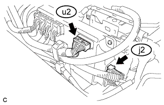
Check the connections of the u2 and j2 connectors of the battery smart unit.
OK The connectors are connected securely and there are no contact problems. -
Install the No. 1 hybrid vehicle battery shield panel.
NG
CONNECT SECURELY
OK
-
-
CHECK INSTALLATION OF INLET AIR TEMPERATURE SENSOR
CAUTION:
Be sure to wear insulated gloves and protective goggles.
-
Check that the service plug grip is not installed.
Note
After removing the service plug grip, do not turn the power switch on (READY), unless instructed by the repair manual because this may cause a malfunction.
-
Remove the No. 1 hybrid vehicle battery shield panel Click here.
-
Visually check the installation condition of the inlet air temperature sensor.
OK The inlet air temperature sensor is installed in the correct location and its claws are engaged securely. Result Result Proceed to The inlet air temperature sensor is installed in the correct location and its claws are engaged securely A Inlet air temperature sensor is not installed correctly or claws are damaged. B -
Install the No. 1 hybrid vehicle battery shield panel.
B
REPLACE NO. 4 HYBRID VEHICLE SUPPLY STACK SUB-ASSEMBLY Click here
A
-
-
CHECK WIRE HARNESS AND CONNECTORS (INLET AIR TEMPERATURE SENSOR)
CAUTION:
Be sure to wear insulated gloves and protective goggles.
-
Check that the service plug grip is not installed.
Note
After removing the service plug grip, do not turn the power switch on (READY), unless instructed by the repair manual because this may cause a malfunction.
-
Remove the upper hybrid battery cover sub-assembly Click here.
-
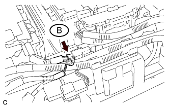
Disconnect the connector B.
-
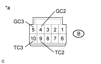
Text in Illustration *a Front view of No. 4 hybrid vehicle supply stack sub-assembly connector
(Intermediate wire harness connector)
Measure the resistance of the circuit for the malfunctioning sensor (battery temperature sensor 0 to 2).
Tester Connection Tester Connection Battery Temperature Sensor No. B-9 (TC2) - B-4 (GC2) 2 B-10 (TC3) - B-5 (GC3) 3 Standard Resistance Thermistor Temperature Condition Specified Condition 0 °C (32 °F) Power switch off 26.7 to 27.8 kΩ 25 °C (77 °F) Power switch off 9.9 to 10.1 kΩ 40 °C (104 °F) Power switch off 5.73 to 5.92 kΩ -
Measure the resistance according to the value(s) in the table below.
Standard Resistance Tester Connection Condition Specified Condition B-9 (TC2) - Body ground and other terminals Power switch off 10 kΩ or higher B-4 (GC2) - Body ground and other terminals Power switch off 10 kΩ or higher B-10 (TC3) - Body ground and other terminals Power switch off 10 kΩ or higher B-5 (GC3) - Body ground and other terminals Power switch off 10 kΩ or higher -
Connect the cable to the negative (-) auxiliary battery terminal.
-
Turn the power switch on (IG).
-
Measure the voltage according to the value(s) in the table below.
Standard Voltage Tester Connection Condition Specified Condition B-9 (TC2) - Body ground Power switch on (IG) 1 V or less B-4 (GC2) - Body ground Power switch on (IG) 1 V or less B-10 (TC3) - Body ground Power switch on (IG) 1 V or less B-5 (GC3) - Body ground Power switch on (IG) 1 V or less Note
Turning the power switch on (IG) with the service grip removed causes other DTCs to be stored. Clear the DTCs after performing this inspection.
-
Turn the power switch off.
-
Disconnect the cable from the negative (-) auxiliary battery terminal.
-
Reconnect the connector B.
-
Install the upper hybrid battery cover sub-assembly.
NG
REPLACE NO. 4 HYBRID VEHICLE SUPPLY STACK SUB-ASSEMBLY Click here
OK
-
-
CHECK HV BATTERY (INLET AIR TEMPERATURE SENSOR)
CAUTION:
Be sure to wear insulated gloves.
-
Check that the service plug grip is not installed.
Note
After removing the service plug grip, do not turn the power switch on (READY), unless instructed by the repair manual because this may cause a malfunction.
-
Remove the No. 1 hybrid vehicle battery shield panel Click here.
-
Remove the No. 1 hybrid battery intake duct Click here.
-
Disconnect the u2 and j2 battery smart unit connectors.
-
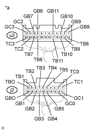
Text in Illustration *a Rear view of wire harness connector
(to Battery Smart Unit)
Measure the resistance according to the value(s) in the table below.
Tester Connection Tester Connection Inlet Air Temperature Sensor No. j2-2(TC0) - j2-12(GC0) 0 j2-1(TC1) - j2-11(GC1) 1 u2-23(TC2) - u2-11(GC2) 2 u2-24(TC3) - u2-12(GC3) 3 Standard Resistance Condition Condition Specified Condition 0 °C (32 °F) Power switch off 26.7 to 27.8 kΩ 25 °C (77 °F) Power switch off 9.9 to 10.1 kΩ 40 °C (104 °F) Power switch off 5.73 to 5.92 kΩ -
Measure the resistance according to the value(s) in the table below.
Standard Resistance Tester Connection Condition Specified Condition j2-2 (TC0) - Body ground and other terminals Power switch off 10 kΩ or higher j2-12 (GC0) - Body ground and other terminals Power switch off 10 kΩ or higher j2-1 (TC1) - Body ground and other terminals Power switch off 10 kΩ or higher j2-11 (GC1) - Body ground and other terminals Power switch off 10 kΩ or higher j2-10 (TBO) - Body ground and other terminals Power switch off 10 kΩ or higher j2-20 (GBO) - Body ground and other terminals Power switch off 10 kΩ or higher j2-9 (TB1) - Body ground and other terminals Power switch off 10 kΩ or higher j2-19 (GB1) - Body ground and other terminals Power switch off 10 kΩ or higher j2-8 (TB2) - Body ground and other terminals Power switch off 10 kΩ or higher j2-18 (GB2) - Body ground and other terminals Power switch off 10 kΩ or higher j2-7 (TB3) - Body ground and other terminals Power switch off 10 kΩ or higher j2-17 (GB3) - Body ground and other terminals Power switch off 10 kΩ or higher j2-6 (TB4) - Body ground and other terminals Power switch off 10 kΩ or higher j2-16 (GB4) - Body ground and other terminals Power switch off 10 kΩ or higher j2-5 (TB5) - Body ground and other terminals Power switch off 10 kΩ or higher j2-15 (GB5) - Body ground and other terminals Power switch off 10 kΩ or higher u2-23 (TC2) - Body ground and other terminals Power switch off 10 kΩ or higher u2-11 (GC2) - Body ground and other terminals Power switch off 10 kΩ or higher u2-24 (TC3) - Body ground and other terminals Power switch off 10 kΩ or higher u2-12 (GC3) - Body ground and other terminals Power switch off 10 kΩ or higher u2-21 (TB6) - Body ground and other terminals Power switch off 10 kΩ or higher u2-9 (GB6) - Body ground and other terminals Power switch off 10 kΩ or higher u2-22 (TB7) - Body ground and other terminals Power switch off 10 kΩ or higher u2-10 (GB7) - Body ground and other terminals Power switch off 10 kΩ or higher u2-13 (TB8) - Body ground and other terminals Power switch off 10 kΩ or higher u2-1 (GB8) - Body ground and other terminals Power switch off 10 kΩ or higher u2-14 (TB9) - Body ground and other terminals Power switch off 10 kΩ or higher u2-2 (GB9) - Body ground and other terminals Power switch off 10 kΩ or higher u2-15 (TB10) - Body ground and other terminals Power switch off 10 kΩ or higher u2-3 (GB10) - Body ground and other terminals Power switch off 10 kΩ or higher u2-17 (TB11) - Body ground and other terminals Power switch off 10 kΩ or higher u2-5 (GB11) - Body ground and other terminals Power switch off 10 kΩ or higher -
Connect the cable to the negative (-) auxiliary battery terminal.
-
Turn the power switch on (IG).
-
Measure the voltage according to the value(s) in the table below.
Standard Voltage Tester Connection Condition Specified Condition j2-2 (TC0) - Body ground Power switch on (IG) Below 1 V j2-12 (GC0) - Body ground Power switch on (IG) Below 1 V j2-1 (TC1) - Body ground Power switch on (IG) Below 1 V j2-11 (GC1) - Body ground Power switch on (IG) Below 1 V j2-10 (TBO) - Body ground Power switch on (IG) Below 1 V j2-20 (GBO) - Body ground Power switch on (IG) Below 1 V j2-9 (TB1) - Body ground Power switch on (IG) Below 1 V j2-19 (GB1) - Body ground Power switch on (IG) Below 1 V j2-8 (TB2) - Body ground Power switch on (IG) Below 1 V j2-18 (GB2) - Body ground Power switch on (IG) Below 1 V j2-7 (TB3) - Body ground Power switch on (IG) Below 1 V j2-17 (GB3) - Body ground Power switch on (IG) Below 1 V j2-6 (TB4) - Body ground Power switch on (IG) Below 1 V j2-16 (GB4) - Body ground Power switch on (IG) Below 1 V j2-5 (TB5) - Body ground Power switch on (IG) Below 1 V j2-15 (GB5) - Body ground Power switch on (IG) Below 1 V u2-23 (TC2) - Body ground Power switch on (IG) Below 1 V u2-11 (GC2) - Body ground Power switch on (IG) Below 1 V u2-24 (TC3) - Body ground Power switch on (IG) Below 1 V u2-12 (GC3) - Body ground Power switch on (IG) Below 1 V u2-21 (TB6) - Body ground Power switch on (IG) Below 1 V u2-9 (GB6) - Body ground Power switch on (IG) Below 1 V u2-22 (TB7) - Body ground Power switch on (IG) Below 1 V u2-10 (GB7) - Body ground Power switch on (IG) Below 1 V u2-13 (TB8) - Body ground Power switch on (IG) Below 1 V u2-1 (GB8) - Body ground Power switch on (IG) Below 1 V u2-14 (TB9) - Body ground Power switch on (IG) Below 1 V u2-2 (GB9) - Body ground Power switch on (IG) Below 1 V u2-15 (TB10) - Body ground Power switch on (IG) Below 1 V u2-3 (GB10) - Body ground Power switch on (IG) Below 1 V u2-17 (TB11) - Body ground Power switch on (IG) Below 1 V u2-5 (GB11) - Body ground Power switch on (IG) Below 1 V Note
Turning the power switch on (IG) with the service grip removed causes other DTCs to be stored. Clear the DTCs after performing this inspection.
-
Turn the power switch off.
-
Disconnect the cable from the negative (-) auxiliary battery terminal.
-
Reconnect the u2 and j2 battery smart unit connectors.
-
Install the No. 1 hybrid battery intake duct.
-
Install the No. 1 hybrid vehicle battery shield panel.
NG
REPLACE NO. 3 HYBRID VEHICLE SUPPLY STACK SUB-ASSEMBLY Click here
OK
-
-
CHECK BATTERY SMART UNIT (VIB VOLTAGE)
CAUTION:
Be sure to wear insulated gloves.
-
Check that the service plug grip is not installed.
Note
After removing the service plug grip, do not turn the power switch on (READY), unless instructed by the repair manual because this may cause a malfunction.
-
Remove the No. 1 hybrid vehicle battery shield panel Click here.
-
Remove the No. 1 hybrid battery intake duct Click here.
-
Connect the cable to the negative (-) auxiliary battery terminal.
-
Turn the power switch on (IG).
-
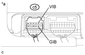
Text in Illustration *a Component with harness connected
(Battery Smart Unit)
Measure the voltage according to the value(s) in the table below.
Standard Voltage Tester Connection Condition Specified Condition c5-2 (VIB) - c5-8 (GIB) Power switch on (IG) 4.6 to 5.4 V Note
Turning the power switch on (IG) with the service grip removed causes other DTCs to be stored. Clear the DTCs after performing this inspection.
-
Turn the power switch off.
-
Disconnect the cable from the negative (-) auxiliary battery terminal.
-
Install the No. 1 hybrid battery intake duct.
-
Install the No. 1 hybrid vehicle battery shield panel.
NG 
OK 
REPLACE BATTERY SMART UNIT Click here
-
-
CHECK HYBRID BATTERY JUNCTION BLOCK ASSEMBLY
CAUTION:
Be sure to wear insulated gloves.
-
Check that the service plug grip is not installed.
Note
After removing the service plug grip, do not turn the power switch on (READY), unless instructed by the repair manual because this may cause a malfunction.
-
Remove the No. 1 hybrid vehicle battery shield panel Click here.
-
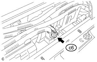
Disconnect the c6 hybrid battery junction block assembly connector.
-
Connect the cable to the negative (-) auxiliary battery terminal.
-
Turn the power switch on (IG).
-

Text in Illustration *a Front view of wire harness connector
(Battery Junction Block Assembly)
Measure the voltage according to the value(s) in the table below.
Standard Voltage Tester Connection Condition Specified Condition c6-1 (VIB) - c6-3 (GIB) Power switch on (IG) 4.6 to 5.4 V Note
Turning the power switch on (IG) with the service grip removed causes other DTCs to be stored. Clear the DTCs after performing this inspection.
-
Turn the power switch off.
-
Disconnect the cable from the negative (-) auxiliary battery terminal.
-
Install the No. 1 hybrid vehicle battery shield panel.
NG
OK
REPLACE HYBRID BATTERY JUNCTION BLOCK ASSEMBLY Click here
-
-
CHECK HARNESS AND CONNECTOR (HYBRID BATTERY JUNCTION BLOCK ASSEMBLY - BATTERY SMART UNIT)
CAUTION:
Be sure to wear insulated gloves.
-
Check that the service plug grip is not installed.
Note
After removing the service plug grip, do not turn the power switch on (READY), unless instructed by the repair manual because this may cause a malfunction.
-
Remove the No. 1 hybrid battery intake duct Click here.
-
Remove the No. 1 hybrid vehicle battery shield panel Click here.
-
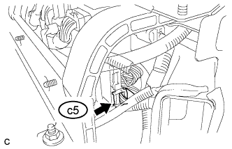
Disconnect only the c5 battery smart unit connector.
-
Disconnect the c6 battery current sensor connector from the hybrid battery junction block assembly.
-
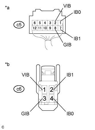
Text in Illustration *a Rear view of wire harness connector
(to Battery Smart Unit)
*b Front view of wire harness connector
(to Hybrid Battery Junction Block Assembly)
Measure the resistance according to the value(s) in the tables below.
Standard Resistance (Check for Open) Tester Connection Condition Specified Condition c5-7 (IB1) - c6- 2 (IB1) Power switch off Below 1 Ω c5-8 (GIB) - c6- 3 (GIB) Power switch off Below 1 Ω c5-1 (IB0) - c6- 4 (IB0) Power switch off Below 1 Ω c5-2 (VIB) - c6- 1 (VIB) Power switch off Below 1 Ω Standard Resistance (Check for Short) Tester Connection Condition Specified Condition c5-7 (IB1) or c6- 2 (IB1) - Body ground and other terminals Power switch off 10 kΩ or higher c5-8 (GIB) or c6- 3 (GIB) - Body ground and other terminals Power switch off 10 kΩ or higher c5-1 (IB0) or c6- 4 (IB0) - Body ground and other terminals Power switch off 10 kΩ or higher c5-2 (VIB) or c6- 1 (VIB) - Body ground and other terminals Power switch off 10 kΩ or higher -
Reconnect the c5 battery smart unit connector.
-
Reconnect the c6 battery current sensor connector to the hybrid battery junction block assembly.
-
Install the No. 1 hybrid battery intake duct.
-
Install the No. 1 hybrid vehicle battery shield panel.
NG
REPAIR HARNESS OR CONNECTOR OR REPLACE HV BATTERY Click here
OK
REPLACE BATTERY SMART UNIT Click here
-