HYBRID BATTERY SYSTEM, Diagnostic DTC:P31AB-123, P1A61-123, P1A64-123, P1A67-123
| DTC Code | DTC Name |
|---|---|
| P31AB-123 | Hybrid Battery Cell Low Voltage |
| P1A61-123 | Hybrid Battery Cell Low Voltage Stack "B" |
| P1A64-123 | Hybrid Battery Cell Low Voltage Stack "C" |
| P1A67-123 | Hybrid Battery Cell Low Voltage Stack "D" |
DESCRIPTION
-
The power management control ECU alerts the driver and performs fail-safe control based on error signals sent from the battery smart unit.
DTC No. INF Code DTC Detection Condition Trouble Area P31AB 123 When battery cells are over discharged
(1 trip detection)
-
No. 1 hybrid vehicle supply stack sub-assembly
-
No. 2 hybrid vehicle supply stack sub-assembly
-
No. 3 hybrid vehicle supply stack sub-assembly
-
No. 4 hybrid vehicle supply stack sub-assembly
-
Power management control ECU
-
Inverter with converter assembly
-
Frame wire
-
Electric vehicle fuse
-
Battery smart unit
-
Hybrid battery junction block assembly
-
Wire harness or connector
-
No. 2 hybrid vehicle battery pack cable
-
No. 3 hybrid vehicle battery pack cable
-
Electric vehicle battery plug assembly
-
No. 6 hybrid vehicle battery terminal
P1A61 P1A64 P1A67 Tech Tips
DTC will not be set unless the vehicle is driven for approximately 10 minutes after clearing the DTC.
-
INSPECTION PROCEDURE
CAUTION:
-
Before inspecting the high-voltage system or disconnecting the low voltage connector of the inverter with converter assembly or electric vehicle charger assembly, turn the power switch off. Also, take safety precautions such as wearing insulated gloves and removing the service plug grip to prevent electrical shocks. After removing the service plug grip, put it in your pocket to prevent other technicians from accidentally reconnecting it while you are working on the high-voltage system.
-
After removing the service plug grip, wait for at least 10 minutes before touching any of the high-voltage connectors or terminals. After waiting for 10 minutes, check the voltage at the terminals in the inspection point in the inverter with converter assembly. The voltage should be 0 V before beginning work Click here.
Tech Tips
Waiting for at least 10 minutes is required to discharge the high-voltage capacitor inside the inverter with converter assembly and electric vehicle charger assembly.
-
When disposing of HV batteries and hybrid vehicle supply stack sub-assemblies, make sure to return them through an authorized collection agent who is capable of handling them safely. If they are returned via the manufacturer specified route, they will be returned properly and in a safe manner by an authorized collection agent.
-
Before returning the HV battery, make sure to perform recovery inspection Click here.
-
Before returning the hybrid vehicle supply stack sub-assembly, make sure to perform recovery inspection Click here.
-
Make a note of the output DTCs as some of them may be necessary for recovery inspection of the HV battery and hybrid vehicle supply stack sub-assemblies.
Note
-
After turning the power switch off, waiting time may be required before disconnecting the cable from the negative (-) auxiliary battery terminal. Therefore, make sure to read the disconnecting the cable from the negative (-) auxiliary battery terminal notices before proceeding with work Click here.
-
After replacing the malfunctioning part, perform "HV Batt Cell Low Volt READY ON Prevention Cancel" and clear the DTCs.
PROCEDURE
-
CHECK DTC OUTPUT (HYBRID CONTROL)
-
Connect the GTS to the DLC3.
-
Turn the power switch on (IG).
-
Enter the following menus: Powertrain / Hybrid Control / Trouble Codes.
-
Read output DTCs Click here.
Result Result Proceed to P301B-123 is not output A P301B-123 is output B -
Turn the power switch off.
B 
GO TO DTC CHART (P301B-123) Click here
A 
-
-
SYSTEM CHECK (HYBRID CONTROL)
CAUTION:
Before repairing or replacing the malfunctioning part, do not perform "HV Batt Cell Low Volt READY ON Prevention Cancel".
-
While depressing the brake pedal, press the power switch and check that the hybrid system turns on (READY).
Note
Do not turn the power switch on (READY) repeatedly. Doing so may cause a malfunction.
Result Result Proceed to Hybrid system starts. A Hybrid system does not start. B -
Turn the power switch off.
B 
DTC OUTPUT (HYBRID CONTROL) Click here
A
-
-
DTC OUTPUT (HYBRID CONTROL)
-
Connect the GTS to the DLC3.
-
Turn the power switch on (IG).
-
Enter the following menus: Powertrain / Hybrid Control / Trouble Codes.
-
Read output DTCs Click here.
Result Result Proceed to P0AFC-123 is not output. A P0AFC-123 is also output. B -
Disconnect the GTS from the DLC3.
B
GO TO DTC CHART (P0AFC-123) Click here
A
-
-
CHECK CONNECTOR CONNECTION CONDITION
CAUTION:
Be sure to wear insulated gloves.
-
Check that the service plug grip is not installed.
Note
After removing the service plug grip, do not turn the power switch on (READY), unless instructed by the repair manual because this may cause a malfunction.
-
Remove the No. 1 hybrid vehicle battery shield panel Click here.
-
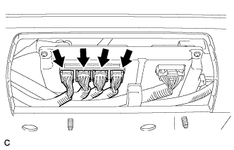
Check the connections of the battery smart unit.
OK The connectors are connected securely and there are no contact problems. -
Install the No. 1 hybrid vehicle battery shield panel.
NG
CONNECT SECURELY
OK
-
-
CHECK DTC OUTPUT (HYBRID CONTROL)
-
Connect the GTS to the DLC3.
-
Turn the power switch on (IG).
-
Enter the following menus: Powertrain / Hybrid Control / Trouble Codes.
-
Read output DTCs Click here.
Result Result Proceed to P31AB-123 is output A P1A61-123 is output B P1A64-123 is output C P1A67-123 is output D -
Turn the power switch off.
A
CHECK HV BATTERY (BATTERY CELL VOLTAGE (STACK 1)) Click here
B
CHECK HV BATTERY (BATTERY CELL VOLTAGE (STACK 2)) Click here
C
CHECK HV BATTERY (BATTERY CELL VOLTAGE (STACK 3)) Click here
D
CHECK HV BATTERY (BATTERY CELL VOLTAGE (STACK 4)) Click here
-
-
DTC OUTPUT (HYBRID CONTROL)
-
Connect the GTS to the DLC3.
-
Turn the power switch on (IG).
-
Enter the following menus: Powertrain / Hybrid Control / Trouble Codes.
-
Record the output DTCs Click here.
Note
Make a note of the DTCs that will be used in step 7, 9.
-
Disconnect the GTS from the DLC3.
-
Turn the power switch off.
NEXT
-
-
REPLACE ALL HYBRID BATTERY VEHICLE SUPPLY STACK SUB-ASSEMBLY
-
Check the note of the output DTCs recorded in step 6 and replace the specified hybrid vehicle supply stack sub-assembly according to the following table Click here.
DTC No. Hybrid Vehicle Supply Stack Sub-assembly to be Replaced P31AB-123 No. 1 hybrid vehicle supply stack sub-assembly P1A61-123 No. 2 hybrid vehicle supply stack sub-assembly P1A64-123 No. 3 hybrid vehicle supply stack sub-assembly P1A67-123 No. 4 hybrid vehicle supply stack sub-assembly
NEXT
-
-
REPLACE BATTERY SMART UNIT
NEXT
-
RECONFIRM DTC OUTPUT (HYBRID CONTROL)
-
Check the DTCs recorded in step 6.
Result Result Proceed to P31B3-123 is not output. A DTCs shown in P31B3-123 and Table 1 are output simultaneously. B DTCs shown in P31B3-123 and Table 1 are not output simultaneously. C Table 1 DTC No. Relevant Diagnosis P0A78-266, 267, 565, 586 Drive Motor "A" Inverter Performance P0A94-564, 585, 587, 589, 590 DC/DC Converter Performance Tech Tips
DTC P31B3-123 may be output simultaneously. In this case, troubleshoot the DTCs listed above first. Then, perform a reproduction test to check that no DTCs are output.
B
GO TO DTC CHART (HYBRID CONTROL SYSTEM) Click here
C
REPLACE POWER MANAGEMENT CONTROL ECU Click here
A
-
-
UTILITY
CAUTION:
Before repairing or replacing the malfunctioning part, do not perform "HV Batt Cell Low Volt READY ON Prevention Cancel".
-
Perform "HV Batt Cell Low Volt READY ON Prevention Cancel" Click here.
NEXT
-
-
CLEAR DTC (HYBRID CONTROL)
-
Connect the GTS to the DLC3.
-
Turn the power switch on (IG).
-
Enter the following menus: Powertrain / Hybrid Control / Trouble Codes.
-
Clear the DTCs and freeze frame data Click here.
Tech Tips
Power source mode does not change to ON (Ready).
-
Disconnect the GTS from the DLC3.
-
Turn the power switch off.
NEXT
-
-
RECONFIRM DTC OUTPUT (HYBRID CONTROL)
-
Perform a driving test for about 10 minutes to allow the ECU to store DTCs. If the hybrid system does not start, turn the power switch off and on (READY).
Tech Tips
Because 2-trip detection logic is used, the DTC detection conditions need to be met twice.
-
Connect the GTS to the DLC3.
-
Turn the power switch on (IG).
-
Enter the following menus: Powertrain / Hybrid Control / Trouble Codes.
-
Read output DTCs Click here.
Result Result Proceed to P31AB-123, P1A61-123, P1A64-123, P1A67-123 is not output A P31AB-123, P1A61-123, P1A64-123, P1A67-123 is output B P3004-131 is output C -
Disconnect the GTS from the DLC3.
-
Turn the power switch off.
B
C
GO TO DTC CHART (P3004-131) Click here
A 
RETURNS TO NORMAL OPERATION
-
-
CHECK CONNECTOR CONNECTION CONDITION (POWER MANAGEMENT CONTROL ECU CONNECTOR)
-
Check the connector connections and contact pressure of the relevant terminals for the power management control ECU connectors Click here.
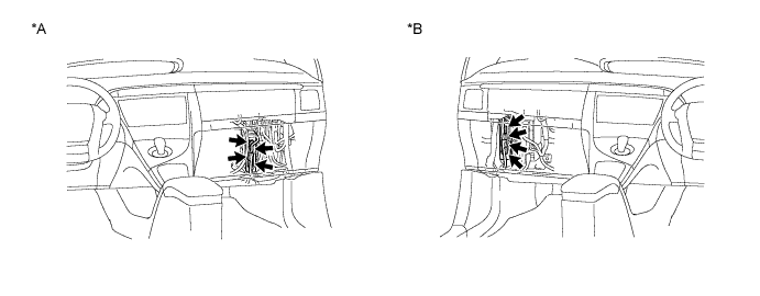
OK The connectors are connected securely and there are no contact pressure problems. Text in Illustration *A for LHD *B for RHD
NG
CONNECT SECURELY
OK
-
-
CHECK FRAME WIRE (INVERTER WITH CONVERTER ASSEMBLY SIDE)
CAUTION:
Be sure to wear insulated gloves.
-
Check that the service plug grip is not installed.
Note
After removing the service plug grip, do not turn the power switch on (READY), unless instructed by the repair manual because this may cause a malfunction.
-
Remove the inverter cover from the inverter with converter assembly.
-
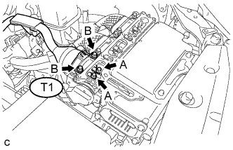
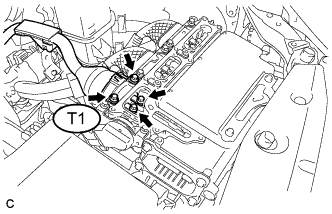
Check the connection between the frame wire T1 and the inverter with converter assembly.
Specified Condition Bolt A 8.0 N*m (82 kgf*cm, 71 in.*lbf) Bolt B 9.2 N*m (94 kgf*cm, 81 in.*lbf) Note
-
Make sure that the tightening torque of the bolt A is between 6.4 and 9.6 N*m (65 and 98 kgf*cm, 57 and 85 in.*lbf).
-
Make sure that the tightening torque of the bolt B is between 6.4 and 12 N*m (65 and 122 kgf*cm, 57 and 106 in.*lbf).
-
-
Disconnect the frame wire T1 from the inverter with converter assembly.
-
Check for arc marks on the terminals of the frame wire.
Result Result Proceed to The terminals are connected securely and there are no contact problems. There are no arc marks. A The terminals are not connected securely and there is a contact problem. There are arc marks. B The terminals are not connected securely and there is a contact problem. There are no arc marks. C The terminals are connected securely and there are no contact problems. There are arc marks. B -
Connect the frame wire.
-
Install the inverter cover to the inverter with converter assembly.
B
REPLACE MALFUNCTIONING PARTS
C
CONNECT SECURELY
A
-
-
CHECK FRAME WIRE (HYBRID BATTERY JUNCTION BLOCK ASSEMBLY SIDE)
CAUTION:
Be sure to wear insulated gloves.
-
Check that the service plug grip is not installed.
Note
After removing the service plug grip, do not turn the power switch on (READY), unless instructed by the repair manual because this may cause a malfunction.
-
Remove the No. 2 hybrid vehicle battery shield panel Click here.
-
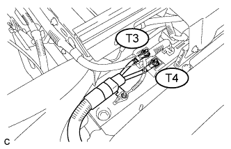
Check the connection between the frame wire T3, T4 and the hybrid battery junction block assembly.
Specified Condition 9.0 N*m (92 kgf*cm, 80 in.*lbf) -
Disconnect the frame wire T3, T4 from the hybrid battery junction block assembly.
-
Check for arc marks on the terminals of the frame wire.
Result Result Proceed to The terminals are connected securely and there are no contact problems. There are no arc marks. A The terminals are not connected securely and there is a contact problem. There are arc marks. B The terminals are not connected securely and there is a contact problem. There are no arc marks. C The terminals are connected securely and there are no contact problems. There are arc marks. B -
Connect the frame wire.
-
Install the No. 2 hybrid vehicle battery shield panel.
B
REPLACE MALFUNCTIONING PARTS
C
CONNECT SECURELY
A
-
-
CHECK FRAME WIRE (INVERTER WITH CONVERTER - HYBRID BATTERY JUNCTION BLOCK)
CAUTION:
Be sure to wear insulated gloves.
-
Check that the service plug grip is not installed.
Note
After removing the service plug grip, do not turn the power switch on (READY), unless instructed by the repair manual because this may cause a malfunction.
-
Remove the inverter cover from the inverter with converter assembly.
-
Disconnect the frame wire T1 from the inverter with converter assembly.
-
Remove the No. 2 hybrid vehicle battery shield panel Click here.
-
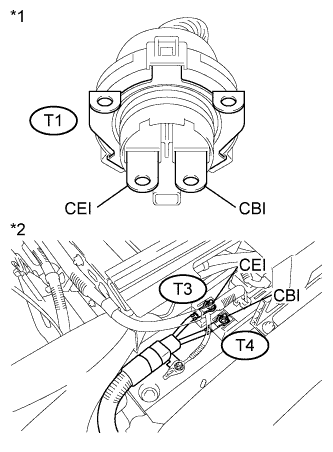
Text in Illustration *1 Frame Wire
(Inverter with Converter Assembly Side)
*2 Frame Wire
(Hybrid Battery Junction Block Assembly Side)
Measure the resistance according to the value(s) in the table below.
Standard Resistance Tester Connection Condition Specified Condition T1-2 (CBI) - T4-1 (CBI) Power switch off Below 1 Ω T1-1 (CEI) - T3-1 (CEI) Power switch off Below 1 Ω -
Install the No. 2 hybrid vehicle battery shield panel.
-
Connect the frame wire.
-
Install the inverter cover to the inverter with converter assembly.
NG
REPLACE FRAME WIRE Click here
OK
-
-
CHECK CONNECTOR CONNECTION CONDITION (HV BATTERY HIGH VOLTAGE CONNECTOR)
CAUTION:
Be sure to wear insulated gloves.
-
Check that the service plug grip is not installed.
Note
After removing the service plug grip, do not turn the power switch on (READY), unless instructed by the repair manual because this may cause a malfunction.
-
Remove the No. 1 hybrid vehicle battery shield panel Click here.
-
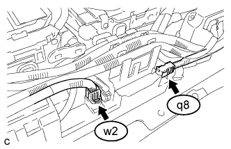
Check the connections between the HV battery high voltage connectors (w2, q8) and the hybrid battery junction block assembly.
OK The connectors are connected securely and not damaged. -
Disconnect connector w2 and q8 of the HV battery high voltage connectors from the hybrid battery junction block assembly.
-
Check for arc marks on the terminals of the HV battery high voltage connectors.
Result Result Proceed to The terminals are connected securely and there are no contact problems. There are no arc marks. A The terminals are not connected securely and there is a contact problem. There are arc marks. B The terminals are not connected securely and there is a contact problem. There are no arc marks. C The terminals are connected securely and there are no contact problems. There are arc marks. B -
Connect the HV battery high voltage connectors.
-
Install the No. 1 hybrid vehicle battery shield panel.
B
REPLACE MALFUNCTIONING PARTS
C
CONNECT SECURELY
A
-
-
CHECK HV BATTERY
CAUTION:
Be sure to wear insulated gloves.
-
Check that the service plug grip is not installed.
Note
After removing the service plug grip, do not turn the power switch on (READY), unless instructed by the repair manual because this may cause a malfunction.
-
Remove the No. 1 hybrid vehicle battery shield panel Click here.
-
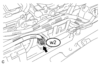
Disconnect the w2 hybrid battery junction block assembly connector.
-
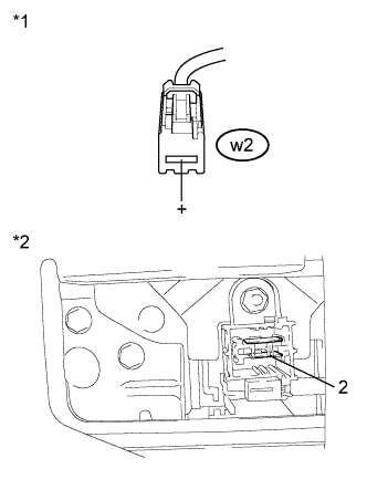
Text in Illustration *1 No. 2 Hybrid Vehicle Battery Pack Cable
(Hybrid Battery Junction Block Assembly Side)
*2 Electric Vehicle Battery Plug Assembly
(Service plug grip Side)
Measure the voltage according to the value(s) in the table below.
Standard Voltage Tester Connection Condition Specified Condition w2-1 (+) - 2 Power switch off 84 V or higher -
Reconnect the w2 hybrid battery junction block assembly connector.
-
Install the No. 1 hybrid vehicle battery shield panel.
NG
OK
-
-
CHECK HV BATTERY
CAUTION:
Be sure to wear insulated gloves.
-
Check that the service plug grip is not installed.
Note
After removing the service plug grip, do not turn the power switch on (READY), unless instructed by the repair manual because this may cause a malfunction.
-
Remove the No. 1 hybrid vehicle battery shield panel Click here.
-
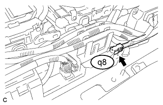
Disconnect the q8 hybrid battery junction block assembly connector.
-
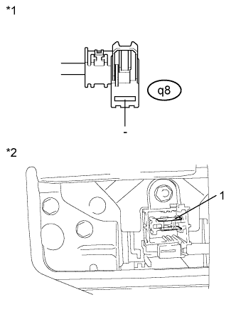
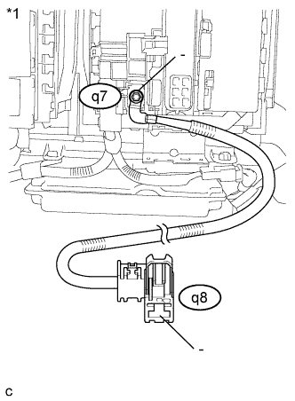
Text in Illustration *1 No. 1 Hybrid Vehicle Battery Pack Cable
(Hybrid Battery Junction Block Assembly Side)
*2 Electric Vehicle Battery Plug Assembly
(Service plug grip Side)
Measure the voltage according to the value(s) in the table below.
Standard Voltage Tester Connection Condition Specified Condition q8-1 (-) - 1 Power switch off 84 V or higher -
Reconnect the q8 hybrid battery junction block assembly connector.
-
Install the No. 1 hybrid vehicle battery shield panel.
NG
OK
-
-
CHECK HARNESS AND CONNECTOR (POWER MANAGEMENT CONTROL ECU - BATTERY PACK WIRE CONNECTOR)
CAUTION:
Be sure to wear insulated gloves.
-
Check that the service plug grip is not installed.
Note
After removing the service plug grip, do not turn the power switch on (READY), unless instructed by the repair manual because this may cause a malfunction.
-
Disconnect the L5 power management control ECU connector.
-
Remove the No. 2 hybrid vehicle battery shield panel Click here.
-
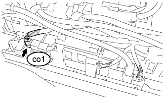
Disconnect the co1 battery pack wire connector.
Tech Tips
Before disconnecting the connector co1 of the battery pack wire connector, make sure that the connector is securely engaged.
-
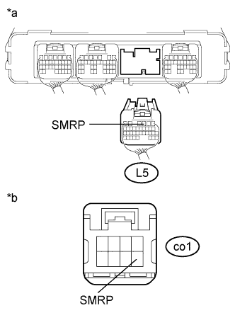
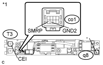
Text in Illustration *a Rear view of wire harness connector
(to Power Management Control ECU)
*b Front view of wire harness connector
(to Battery Pack Wire Connector)
Measure the resistance according to the value(s) in the table below.
Standard Resistance Tester Connection Condition Specified Condition L5-3 (SMRP) - co1-8 (SMRP) Power switch off Below 1 Ω -
Reconnect the co1 battery pack wire connector.
-
Install the No. 2 hybrid vehicle battery shield panel.
-
Reconnect the L5 power management control ECU connector.
NG
REPAIR OR REPLACE HARNESS OR CONNECTOR
OK
-
-
CHECK HARNESS AND CONNECTOR (POWER MANAGEMENT CONTROL ECU - HYBRID BATTERY JUNCTION BLOCK ASSEMBLY)
CAUTION:
Be sure to wear insulated gloves.
-
Check that the service plug grip is not installed.
Note
After removing the service plug grip, do not turn the power switch on (READY), unless instructed by the repair manual because this may cause a malfunction.
-
Disconnect the L5 power management control ECU connector.
-
Remove the No. 1 hybrid vehicle battery shield panel Click here.
-
Disconnect the c9 hybrid battery junction block assembly connector.
Tech Tips
Before disconnecting the connector c9 of the hybrid battery junction block assembly connector, make sure that the connector is securely engaged.
-
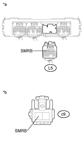
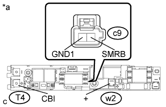
Text in Illustration *a Rear view of wire harness connector
(to Power Management Control ECU)
*b Front view of wire harness connector
(to Hybrid Battery Junction Block Assembly)
Measure the resistance according to the value(s) in the table below.
Standard Resistance Tester Connection Condition Specified Condition L5-4 (SMRB) - c9-1 (SMRB) Power switch off Below 1 Ω -
Reconnect the c9 hybrid battery junction block assembly connector.
-
Install the No. 1 hybrid vehicle battery shield panel.
-
Reconnect the L5 power management control ECU connector.
NG
REPAIR OR REPLACE HARNESS OR CONNECTOR
OK
-
-
INSPECT HYBRID BATTERY JUNCTION BLOCK ASSEMBLY (SMRP)
CAUTION:
Be sure to wear insulated gloves.
-
Check that the service plug grip is not installed.
Note
After removing the service plug grip, do not turn the power switch on (READY), unless instructed by the repair manual because this may cause a malfunction.
-
Remove the No. 1 hybrid vehicle battery shield panel Click here.
-
Disconnect the T3 and T4 hybrid battery junction block assembly terminals.
-
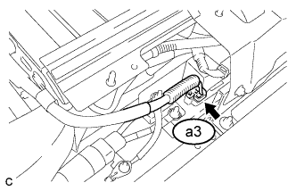
Disconnect the a3 hybrid battery junction block assembly connector.
-
Disconnect the w2 and q8 hybrid battery junction block assembly connector.
-
Disconnect the co1 battery pack wire connector
-
Text in Illustration *1 Hybrid Battery Junction Block Assembly Measure the resistance according to the value(s) in the table below.
Standard Resistance Tester Connection Condition Specified Condition T3-1 (CEI) - q8-1 (-) Auxiliary battery voltage is applied between terminals co1-8 (SMRP) and co1-7 (GND2) 28.5 to 31.5 Ω -
Measure the resistance according to the value(s) in the table below.
Standard Resistance Tester Connection Condition Specified Condition co1-8 (SMRP) - co1-7 (GND2) -40 to 80 °C (-40 to 176°F) 112 to 274 Ω -
Reconnect the co1 battery pack wire connector.
-
Reconnect the a3, w2 and q8 hybrid battery junction block assembly connectors.
-
Reconnect the T3 and T4 hybrid battery junction block assembly terminals.
-
Install the No. 1 hybrid vehicle battery shield panel.
NG
OK
-
-
INSPECT HYBRID BATTERY JUNCTION BLOCK ASSEMBLY (SMRB)
CAUTION:
Be sure to wear insulated gloves.
-
Check that the service plug grip is not installed.
Note
After removing the service plug grip, do not turn the power switch on (READY), unless instructed by the repair manual because this may cause a malfunction.
-
Remove the hybrid battery junction block assembly Click here.
-
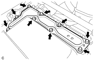
Text in Illustration *a Component without harness connected
(Hybrid Battery Junction Block Assembly)
Measure the resistance according to the value(s) in the table below.
Standard Resistance Tester Connection Condition Specified Condition T4-1 (CBI) - w2-1 (+) Auxiliary battery voltage is applied between terminals c9-1 (SMRB) and c9-2 (GND1) Below 1 Ω -
Measure the resistance according to the value(s) in the table below.
Standard Resistance Tester Connection Condition Specified Condition c9-1 (SMRB) - c9-2 (GND1) 20 °C (68 °F) 30.6 to 37.4 Ω -
Install the hybrid battery junction block assembly.
NG
REPLACE HYBRID BATTERY JUNCTION BLOCK ASSEMBLY Click here
OK
-
-
CHECK INTERMITTENT PROBLEMS
-
Check for intermittent problems Click here.
Result Result Proceed to Problem symptom does not recur. A Problem symptom recurs. B Tech Tips
-
Since 2 trip detection logic is used, the DTC detection condition must be met twice.
-
If DTC P3004-131 is output again after performing the inspection, replace the inverter with converter assembly parts. If DTC P3004-131 is not output again, replace the hybrid battery junction block assembly.
-
B
REPLACE INVERTER WITH CONVERTER ASSEMBLY Click here
A
REPLACE HYBRID BATTERY JUNCTION BLOCK ASSEMBLY Click here
-
-
CHECK HARNESS AND CONNECTOR (BATTERY PACK WIRE CONNECTOR - HYBRID BATTERY JUNCTION BLOCK)
CAUTION:
Be sure to wear insulated gloves and protective goggles.
-
Check that the service plug grip is not installed.
Note
After removing the service plug grip, do not turn the power switch on (READY), unless instructed by the repair manual because this may cause a malfunction.
-
Remove the upper hybrid battery cover sub-assembly Click here.
-
Disconnect the co1 battery pack wire connector.
-
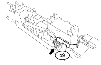
Disconnect the o9 hybrid battery junction block assembly connector.
-
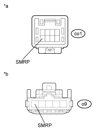
Text in Illustration *a Front view of wire harness connector
(to Battery Pack Wire Connector)
*b Front view of wire harness connector
(to Hybrid Battery Junction Block Assembly)
Measure the resistance according to the value(s) in the table below.
Standard Resistance Tester Connection Condition Specified Condition co1-8 (SMRP) - o9-1 (SMRP) Power switch off Below 1 Ω -
Reconnect the o9 hybrid battery junction block assembly connector.
-
Reconnect the co1 battery pack wire connector.
-
Install the upper hybrid battery cover sub-assembly.
NG
REPAIR OR REPLACE HARNESS OR CONNECTOR
OK
REPLACE HYBRID BATTERY JUNCTION BLOCK ASSEMBLY Click here
-
-
CHECK HV BATTERY (HV BATTERY TERMINAL)
CAUTION:
Be sure to wear insulated gloves and protective goggles.
-
Check that the service plug grip is not installed.
Note
After removing the service plug grip, do not turn the power switch on (READY), unless instructed by the repair manual because this may cause a malfunction.
-
Remove the upper hybrid battery cover sub-assembly Click here.
-
Check for arc marks on the terminals of the HV battery.
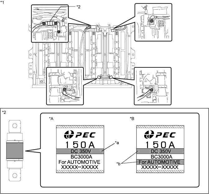
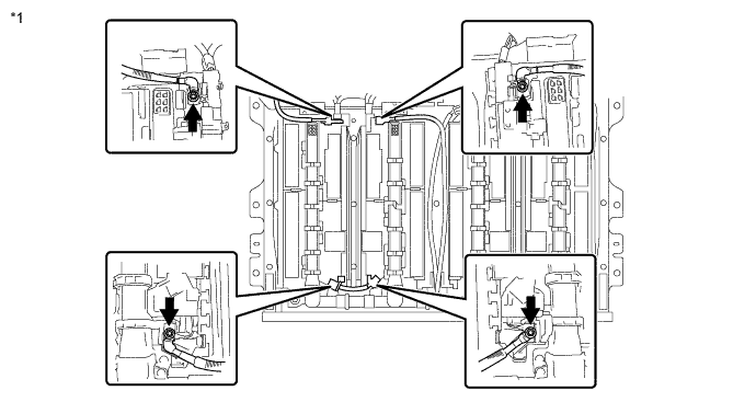
Text in Illustration *A Electric Vehicle Fuse Type A *B Electric Vehicle Fuse Type B *1 HV Battery *2 Electric Vehicle Fuse *a Number of horizontal lines: 1 *b Number of horizontal lines: 2 Specified Condition Nut 5.0 N*m (51 kgf*cm, 44 in.*lbf) Bolt (Electric vehicle fuse type A) 5.0 N*m (51 kgf*cm, 44 in.*lbf) Bolt (Electric vehicle fuse type B) 6.2 N*m (63 kgf*cm, 55 in.*lbf) Tech Tips
The type of the electric vehicle fuse (A or B) can be confirmed by the number of horizontal lines indicated on its label.
-
Check for arc marks on the terminals of the HV battery.
Result Result Proceed to The terminals are connected securely and there are no contact problems. There are no arc marks. A The terminals are not connected securely and there is a contact problem. There are arc marks. B The terminals are not connected securely and there is a contact problem. There are no arc marks. C The terminals are connected securely and there are no contact problems. There are arc marks. B -
Install the upper hybrid battery cover sub-assembly.
B
REPLACE MALFUNCTIONING PARTS
C
CONNECT SECURELY
A
-
-
CHECK ELECTRIC VEHICLE FUSE
CAUTION:
Be sure to wear insulated gloves and protective goggles.
-
Check that the service plug grip is not installed.
Note
After removing the service plug grip, do not turn the power switch on (READY), unless instructed by the repair manual because this may cause a malfunction.
-
Remove the upper hybrid battery cover sub-assembly Click here.
-
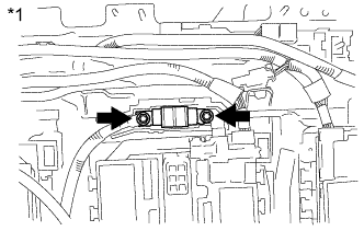
Text in Illustration *1 Electric Vehicle Fuse Measure the resistance according to the value(s) in the table below.
Standard Resistance Tester Connection Condition Specified Condition Electric vehicle fuse Power switch off Below 1 Ω -
Install the upper hybrid battery cover sub-assembly.
NG
REPLACE ELECTRIC VEHICLE FUSE Click here
OK
-
-
CHECK NO. 2 HYBRID VEHICLE BATTERY PACK CABLE
CAUTION:
Be sure to wear insulated gloves and protective goggles.
-
Check that the service plug grip is not installed.
Note
After removing the service plug grip, do not turn the power switch on (READY), unless instructed by the repair manual because this may cause a malfunction.
-
Remove the upper hybrid battery cover sub-assembly Click here.
-
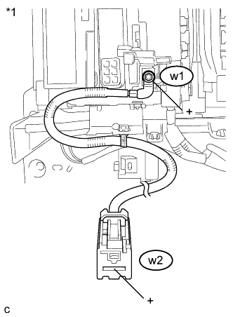
Text in Illustration *1 No. 2 Hybrid Vehicle Battery Pack Cable Measure the resistance according to the value(s) in the table below.
Standard Resistance Tester Connection Condition Specified Condition w1-1 (+) - w2-1 (+) Power switch off Below 1 Ω -
Install the upper hybrid battery cover sub-assembly.
NG
REPLACE NO. 2 HYBRID VEHICLE BATTERY PACK CABLE Click here
OK
-
-
CHECK NO. 3 HYBRID VEHICLE BATTERY PACK CABLE (NO. 3 HYBRID VEHICLE SUPPLY STACK - NO. 4 HYBRID VEHICLE SUPPLY STACK)
CAUTION:
Be sure to wear insulated gloves and protective goggles.
-
Check that the service plug grip is not installed.
Note
After removing the service plug grip, do not turn the power switch on (READY), unless instructed by the repair manual because this may cause a malfunction.
-
Remove the upper hybrid battery cover sub-assembly Click here.
-
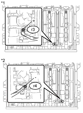
Text in Illustration *1 No. 3 Hybrid Vehicle Battery Pack Cable
(No. 3 Hybrid Vehicle Supply Stack Sub-assembly Side)
*2 No. 3 Hybrid Vehicle Battery Pack Cable
(No. 4 Hybrid Vehicle Supply Stack Sub-assembly Side)
Measure the resistance according to the value(s) in the table below.
Standard Resistance Tester Connection Condition Specified Condition r3-1 (+) - r4-1 (-) Power switch off Below 1 Ω -
Install the upper hybrid battery cover sub-assembly.
NG
REPLACE NO. 3 HYBRID VEHICLE BATTERY PACK CABLE Click here
OK
-
-
CHECK ELECTRIC VEHICLE BATTERY PLUG ASSEMBLY
CAUTION:
Be sure to wear insulated gloves and protective goggles.
-
Check that the service plug grip is not installed.
Note
After removing the service plug grip, do not turn the power switch on (READY), unless instructed by the repair manual because this may cause a malfunction.
-
Remove the upper hybrid battery cover sub-assembly Click here.
-
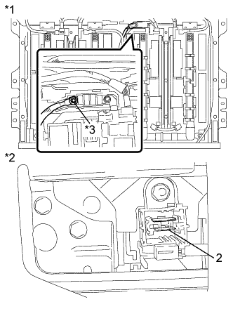
Text in Illustration *1 Electric Vehicle Battery Plug Assembly
(Electric Vehicle Fuse Side)
*2 Electric Vehicle Battery Plug Assembly
(Service Plug Grip Side)
*3 Electric Vehicle Fuse Installation Point Measure the resistance according to the value(s) in the table below.
Standard Resistance Tester Connection Condition Specified Condition Electric vehicle fuse installation point - 2 Power switch off Below 1 Ω -
Install the upper hybrid battery cover sub-assembly.
NG
REPLACE ELECTRIC VEHICLE BATTERY PLUG ASSEMBLY Click here
OK
-
-
CHECK NO. 6 HYBRID VEHICLE BATTERY TERMINAL
CAUTION:
Be sure to wear insulated gloves and protective goggles.
-
Check that the service plug grip is not installed.
Note
After removing the service plug grip, do not turn the power switch on (READY), unless instructed by the repair manual because this may cause a malfunction.
-
Remove the upper hybrid battery cover sub-assembly Click here.
-
Text in Illustration *1 No. 6 Hybrid Vehicle Battery Terminal *2 Electric Vehicle Fuse Installation Point Measure the resistance according to the value(s) in the table below.
Standard Resistance Tester Connection Condition Specified Condition Electric vehicle fuse installation - A-1 Power switch off Below 1 Ω -
Install the upper hybrid battery cover sub-assembly.
NG
REPLACE NO. 6 HYBRID VEHICLE BATTERY TERMINAL Click here
OK
-
-
CHECK NO. 3 HYBRID VEHICLE SUPPLY STACK SUB-ASSEMBLY
CAUTION:
Be sure to wear insulated gloves and protective goggles.
-
Check that the service plug grip is not installed.
Note
After removing the service plug grip, do not turn the power switch on (READY), unless instructed by the repair manual because this may cause a malfunction.
-
Remove the upper hybrid battery cover sub-assembly Click here.
-
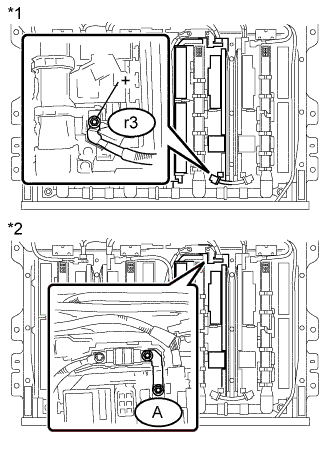
Text in Illustration *1 No. 3 Hybrid Vehicle Battery Pack Cable
(No. 3 Hybrid Vehicle Supply Stack Sub-assembly Side)
*2 No. 6 Hybrid Vehicle Battery terminal
(No. 3 Hybrid Vehicle Supply Stack Sub-assembly Side)
Measure the voltage according to the value(s) in the table below.
Standard Voltage Tester Connection Condition Specified Condition r3-1 (+) - A-1 Power switch off 42 V or higher -
Install the upper hybrid battery cover sub-assembly.
NG
REPLACE NO. 3 HYBRID VEHICLE SUPPLY STACK SUB-ASSEMBLY Click here
OK
REPLACE NO. 4 HYBRID VEHICLE SUPPLY STACK SUB-ASSEMBLY Click here
-
-
CHECK HV BATTERY (HV BATTERY TERMINAL)
CAUTION:
Be sure to wear insulated gloves and protective goggles.
-
Check that the service plug grip is not installed.
Note
After removing the service plug grip, do not turn the power switch on (READY), unless instructed by the repair manual because this may cause a malfunction.
-
Remove the upper hybrid battery cover sub-assembly Click here.
-
Check for arc marks on the terminals of the HV battery.
Text in Illustration *1 HV battery - - Specified Condition 5.0 N*m (51 kgf*cm, 44 in.*lbf) -
Check for arc marks on the terminals of the HV battery.
Result Result Proceed to The terminals are connected securely and there are no contact problems. There are no arc marks. A The terminals are not connected securely and there is a contact problem. There are arc marks. B The terminals are not connected securely and there is a contact problem. There are no arc marks. C The terminals are connected securely and there are no contact problems. There are arc marks. B -
Install the upper hybrid battery cover sub-assembly.
B
REPLACE MALFUNCTIONING PARTS
C
CONNECT SECURELY
A
-
-
CHECK NO. 1 HYBRID VEHICLE BATTERY PACK CABLE
CAUTION:
Be sure to wear insulated gloves and protective goggles.
-
Check that the service plug grip is not installed.
Note
After removing the service plug grip, do not turn the power switch on (READY), unless instructed by the repair manual because this may cause a malfunction.
-
Remove the upper hybrid battery cover sub-assembly Click here.
-
Text in Illustration *1 No. 1 Hybrid Vehicle Battery Pack Cable Measure the resistance according to the value(s) in the table below.
Standard Resistance Tester Connection Condition Specified Condition q7-1 (-) - q8-1 (-) Power switch off Below 1 Ω -
Install the upper hybrid battery cover sub-assembly.
NG
REPLACE NO. 1 HYBRID VEHICLE BATTERY PACK CABLE Click here
OK
-
-
CHECK NO. 3 HYBRID VEHICLE BATTERY PACK CABLE (NO. 1 HYBRID VEHICLE SUPPLY STACK - NO. 2 HYBRID VEHICLE SUPPLY STACK)
CAUTION:
Be sure to wear insulated gloves and protective goggles.
-
Check that the service plug grip is not installed.
Note
After removing the service plug grip, do not turn the power switch on (READY), unless instructed by the repair manual because this may cause a malfunction.
-
Remove the upper hybrid battery cover sub-assembly Click here.
-
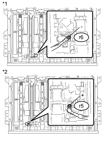
Text in Illustration *1 No. 3 Hybrid Vehicle Battery Pack Cable
(No. 2 Hybrid Vehicle Supply Stack Sub-assembly Side)
*2 No. 3 Hybrid Vehicle Battery Pack Cable
(No. 1 Hybrid Vehicle Supply Stack Sub-assembly Side)
Measure the resistance according to the value(s) in the table below.
Standard Resistance Tester Connection Condition Specified Condition r6-1 (-) - r5-1 (+) Power switch off Below 1 Ω -
Install the upper hybrid battery cover sub-assembly.
NG
REPLACE NO. 3 HYBRID VEHICLE BATTERY PACK CABLE Click here
OK
-
-
CHECK ELECTRIC VEHICLE BATTERY PLUG ASSEMBLY
CAUTION:
Be sure to wear insulated gloves and protective goggles.
-
Check that the service plug grip is not installed.
Note
After removing the service plug grip, do not turn the power switch on (READY), unless instructed by the repair manual because this may cause a malfunction.
-
Remove the upper hybrid battery cover sub-assembly Click here.
-
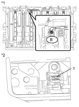
Text in Illustration *1 Electric Vehicle Battery Plug Assembly
(No. 2 Hybrid Vehicle Supply Stack Sub-assembly Side)
*2 Electric Vehicle Battery Plug Assembly
(Service Plug Grip Side)
Measure the resistance according to the value(s) in the table below.
Standard Resistance Tester Connection Condition Specified Condition B-1 - 1 Power switch off Below 1 Ω -
Install the upper hybrid battery cover sub-assembly.
NG
REPLACE ELECTRIC VEHICLE BATTERY PLUG ASSEMBLY Click here
OK
-
-
CHECK NO. 2 HYBRID VEHICLE SUPPLY STACK SUB-ASSEMBLY
CAUTION:
Be sure to wear insulated gloves and protective goggles.
-
Check that the service plug grip is not installed.
Note
After removing the service plug grip, do not turn the power switch on (READY), unless instructed by the repair manual because this may cause a malfunction.
-
Remove the upper hybrid battery cover sub-assembly Click here.
-
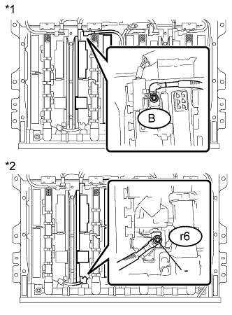
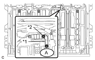
Text in Illustration *1 Electric Vehicle Battery Plug Assembly
(No. 2 Hybrid Vehicle Supply Stack Sub-assembly Side)
*2 No. 3 Hybrid Vehicle Battery Pack Cable
(No. 2 Hybrid Vehicle Supply Stack Sub-assembly Side)
Measure the voltage according to the value(s) in the table below.
Standard Voltage Tester Connection Condition Specified Condition B-1 - r6-1 (-) Power switch off 42 V or higher -
Install the upper hybrid battery cover sub-assembly.
NG
REPLACE NO. 2 HYBRID VEHICLE SUPPLY STACK SUB-ASSEMBLY Click here
OK
REPLACE NO. 1 HYBRID VEHICLE SUPPLY STACK SUB-ASSEMBLY Click here
-
-
CHECK HV BATTERY (BATTERY CELL VOLTAGE (STACK 1))
CAUTION:
Be sure to wear insulated gloves.
-
2012/05 - 2013/12:
-
Check that the service plug grip is not installed.
Note
After removing the service plug grip, do not turn the power switch on (READY), unless instructed by the repair manual because this may cause a malfunction.
-
Remove the No. 1 hybrid vehicle battery shield panel Click here.
-
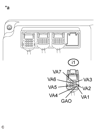
Text in Illustration *a Rear view of wire harness connector
(to Battery Smart Unit)

Text in Illustration *a Rear view of wire harness connector
(to Battery Smart Unit)
Measure the voltage according to the value(s) in the table below.
Standard Voltage (Battery Block 0) Tester Connection Condition Specified Condition i1-13 (GAO) - i1-9 (VA1) Power switch off 3.0 V or more i1-9 (VA1) - i1-5 (VA2) Power switch off 3.0 V or more i1-5 (VA2) - i1-1 (VA3) Power switch off 3.0 V or more i1-1 (VA3) - i1-14 (VA4) Power switch off 3.0 V or more i1-14 (VA4) - i1-10 (VA5) Power switch off 3.0 V or more i1-10 (VA5) - i1-6 (VA6) Power switch off 3.0 V or more i1-6 (VA6) - i1-2 (VA7) Power switch off 3.0 V or more Standard Voltage (Battery Block 1) Tester Connection Condition Specified Condition i1-2 (VA7) - i1-15 (VA8) Power switch off 3.0 V or more i1-15 (VA8) - i1-11 (VA9) Power switch off 3.0 V or more i1-11 (VA9) - i1-7 (VA10 Power switch off 3.0 V or more i1-7 (VA10) - i1-16 (VA11) Power switch off 3.0 V or more i1-16 (VA11) - i1-12 (VA12) Power switch off 3.0 V or more i1-12 (VA12) - i1-8 (VA13) Power switch off 3.0 V or more i1-8 (VA13) - i1-4 (VA14) Power switch off 3.0 V or more Result Result Proceed to The difference between the highest and lowest value is less than 0.3 V and every measured value is 3.0 V or more. A Other than above. B Note
Make sure to check the polarity of each terminal (positive (+) or negative (-)) before connecting a tester.
-
Install the No. 1 hybrid vehicle battery shield panel.
-
-
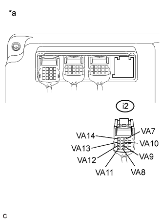
2013/12 -:
-
Check that the service plug grip is not installed.
Note
After removing the service plug grip, do not turn the power switch on (READY), unless instructed by the repair manual because this may cause a malfunction.
-
Remove the No. 1 hybrid vehicle battery shield panel Click here.
-

Text in Illustration *a Rear view of wire harness connector
(to Battery Smart Unit)
Text in Illustration *a Rear view of wire harness connector
(to Battery Smart Unit)
Measure the voltage according to the value(s) in the table below.
Standard Voltage (Battery Block 0) Tester Connection Condition Specified Condition i2-13 (GAO) - i2-9 (VA1) Power switch off 3.0 V or more i2-9 (VA1) - i2-5 (VA2) Power switch off 3.0 V or more i2-5 (VA2) - i2-1 (VA3) Power switch off 3.0 V or more i2-1 (VA3) - i2-14 (VA4) Power switch off 3.0 V or more i2-14 (VA4) - i2-10 (VA5) Power switch off 3.0 V or more i2-10 (VA5) - i2-6 (VA6) Power switch off 3.0 V or more i2-6 (VA6) - i2-2 (VA7) Power switch off 3.0 V or more Standard Voltage (Battery Block 1) Tester Connection Condition Specified Condition i2-2 (VA7) - i2-15 (VA8) Power switch off 3.0 V or more i2-15 (VA8) - i2-11 (VA9) Power switch off 3.0 V or more i2-11 (VA9) - i2-7 (VA10 Power switch off 3.0 V or more i2-7 (VA10) - i2-16 (VA11) Power switch off 3.0 V or more i2-16 (VA11) - i2-12 (VA12) Power switch off 3.0 V or more i2-12 (VA12) - i2-8 (VA13) Power switch off 3.0 V or more i2-8 (VA13) - i2-4 (VA14) Power switch off 3.0 V or more Result Result Proceed to The difference between the highest and lowest value is less than 0.3 V and every measured value is 3.0 V or more. A Other than above. B Note
Make sure to check the polarity of each terminal (positive (+) or negative (-)) before connecting a tester.
-
Install the No. 1 hybrid vehicle battery shield panel.
-
B
REPLACE NO. 1 HYBRID VEHICLE SUPPLY STACK SUB-ASSEMBLY Click here
A
RETURNS TO NORMAL OPERATION
-
-
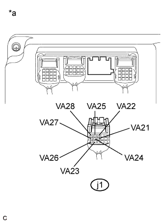
CHECK HV BATTERY (BATTERY CELL VOLTAGE (STACK 2))
CAUTION:
Be sure to wear insulated gloves.
-
2012/05 - 2013/12:
-
Check that the service plug grip is not installed.
Note
After removing the service plug grip, do not turn the power switch on (READY), unless instructed by the repair manual because this may cause a malfunction.
-
Remove the No. 1 hybrid vehicle battery shield panel Click here.
-
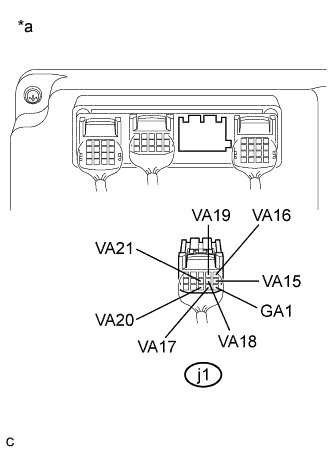
Text in Illustration *a Rear view of wire harness connector
(to Battery Smart Unit)
Text in Illustration *a Rear view of wire harness connector
(to Battery Smart Unit)
Measure the voltage according to the value(s) in the table below.
Standard Voltage (Battery Block 2) Tester Connection Condition Specified Condition j1-11 (GA1) - j1-6 (VA15) Power switch off 3.0 V or more j1-6 (VA15) - j1-1 (VA16) Power switch off 3.0 V or more j1-1 (VA16) - j1- 12 (VA17) Power switch off 3.0 V or more j1-12 (VA17) - j1- 7 (VA18) Power switch off 3.0 V or more j1-7 (VA18) - j1-2 (VA19) Power switch off 3.0 V or more j1-2 (VA19) - j1- 13 (VA20) Power switch off 3.0 V or more j1-13 (VA20) - j1- 8 (VA21) Power switch off 3.0 V or more Standard Voltage (Battery Block 3) Tester Connection Condition Specified Condition j1-8 (VA21) - j1-3 (VA22) Power switch off 3.0 V or more j1-3 (VA22) - j1- 14 (VA23) Power switch off 3.0 V or more j1-14 (VA23) - j1- 9 (VA24) Power switch off 3.0 V or more j1-9 (VA24) - j1-4 (VA25) Power switch off 3.0 V or more j1-4 (VA25) - j1- 15 (VA26) Power switch off 3.0 V or more j1-15 (VA26) - j1- 10 (VA27) Power switch off 3.0 V or more j1-10 (VA27) - j1- 5 (VA28) Power switch off 3.0 V or more Result Result Proceed to The difference between the highest and lowest value is less than 0.3 V and every measured value is 3.0 V or more. A Other than above. B Note
Make sure to check the polarity of each terminal (positive (+) or negative (-)) before connecting a tester.
-
Install the No. 1 hybrid vehicle battery shield panel.
-
-
2013/12 -:
-
Check that the service plug grip is not installed.
Note
After removing the service plug grip, do not turn the power switch on (READY), unless instructed by the repair manual because this may cause a malfunction.
-
Remove the No. 1 hybrid vehicle battery shield panel Click here.
-
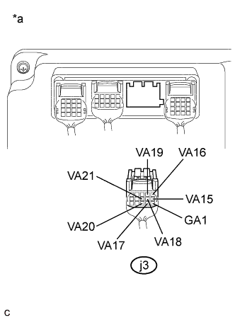
Text in Illustration *a Rear view of wire harness connector
(to Battery Smart Unit)
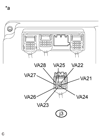
Text in Illustration *a Rear view of wire harness connector
(to Battery Smart Unit)
Measure the voltage according to the value(s) in the table below.
Standard Voltage (Battery Block 2) Tester Connection Condition Specified Condition j3-11 (GA1) - j3-6 (VA15) Power switch off 3.0 V or more j3-6 (VA15) - j3-1 (VA16) Power switch off 3.0 V or more j3-1 (VA16) - j3- 12 (VA17) Power switch off 3.0 V or more j3-12 (VA17) - j3- 7 (VA18) Power switch off 3.0 V or more j3-7 (VA18) - j3-2 (VA19) Power switch off 3.0 V or more j3-2 (VA19) - j3- 13 (VA20) Power switch off 3.0 V or more j3-13 (VA20) - j3- 8 (VA21) Power switch off 3.0 V or more Standard Voltage (Battery Block 3) Tester Connection Condition Specified Condition j3-8 (VA21) - j3-3 (VA22) Power switch off 3.0 V or more j3-3 (VA22) - j3- 14 (VA23) Power switch off 3.0 V or more j3-14 (VA23) - j3- 9 (VA24) Power switch off 3.0 V or more j3-9 (VA24) - j3-4 (VA25) Power switch off 3.0 V or more j3-4 (VA25) - j3- 15 (VA26) Power switch off 3.0 V or more j3-15 (VA26) - j3- 10 (VA27) Power switch off 3.0 V or more j3-10 (VA27) - j3- 5 (VA28) Power switch off 3.0 V or more Result Result Proceed to The difference between the highest and lowest value is less than 0.3 V and every measured value is 3.0 V or more. A Other than above. B Note
Make sure to check the polarity of each terminal (positive (+) or negative (-)) before connecting a tester.
-
Install the No. 1 hybrid vehicle battery shield panel.
-
B
REPLACE NO. 2 HYBRID VEHICLE SUPPLY STACK SUB-ASSEMBLY Click here
A
RETURNS TO NORMAL OPERATION
-
-
CHECK HV BATTERY (BATTERY CELL VOLTAGE (STACK 3))
CAUTION:
Be sure to wear insulated gloves.
-
2012/05 - 2013/12:
-
Check that the service plug grip is not installed.
Note
After removing the service plug grip, do not turn the power switch on (READY), unless instructed by the repair manual because this may cause a malfunction.
-
Remove the No. 1 hybrid vehicle battery shield panel Click here.
-

Text in Illustration *a Rear view of wire harness connector
(to Battery Smart Unit)
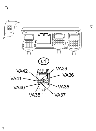
Text in Illustration *a Rear view of wire harness connector
(to Battery Smart Unit)
Measure the voltage according to the value(s) in the table below.
Standard Voltage (Battery Block 4) Tester Connection Condition Specified Condition u1-11 (GA2) - u1-6 (VA29) Power switch off 3.0 V or more u1-6 (VA29) - u1-1 (VA30) Power switch off 3.0 V or more u1-1 (VA30) - u1-12 (VA31) Power switch off 3.0 V or more u1-12 (VA31) - u1-7 (VA32) Power switch off 3.0 V or more u1-7 (VA32) - u1-2 (VA33) Power switch off 3.0 V or more u1-2 (VA33) - u1-13 (VA34) Power switch off 3.0 V or more u1-13 (VA34) - u1-8 (VA35) Power switch off 3.0 V or more Standard Voltage (Battery Block 5) Tester Connection Condition Specified Condition u1-8 (VA35) - u1-3 (VA36) Power switch off 3.0 V or more u1-3 (VA36) - u1-14 (VA37) Power switch off 3.0 V or more u1-14 (VA37) - u1-9 (VA38) Power switch off 3.0 V or more u1-9 (VA38) - u1-4 (VA39) Power switch off 3.0 V or more u1-4 (VA39) - u1-15 (VA40) Power switch off 3.0 V or more u1-15 (VA40) - u1- 10 (VA41) Power switch off 3.0 V or more u1-10 (VA41) - u1-5 (VA42) Power switch off 3.0 V or more Result Result Proceed to The difference between the highest and lowest value is less than 0.3 V and every measured value is 3.0 V or more. A Other than above. B Note
Make sure to check the polarity of each terminal (positive (+) or negative (-)) before connecting a tester.
-
Install the No. 1 hybrid vehicle battery shield panel.
-
-
2013/12 -:
-
Check that the service plug grip is not installed.
Note
After removing the service plug grip, do not turn the power switch on (READY), unless instructed by the repair manual because this may cause a malfunction.
-
Remove the No. 1 hybrid vehicle battery shield panel Click here.
-
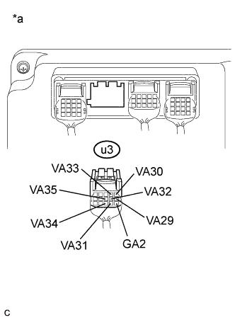
Text in Illustration *a Rear view of wire harness connector
(to Battery Smart Unit)

Text in Illustration *a Rear view of wire harness connector
(to Battery Smart Unit)
Measure the voltage according to the value(s) in the table below.
Standard Voltage (Battery Block 4) Tester Connection Condition Specified Condition u3-11 (GA2) - u3-6 (VA29) Power switch off 3.0 V or more u3-6 (VA29) - u3-1 (VA30) Power switch off 3.0 V or more u3-1 (VA30) - u3-12 (VA31) Power switch off 3.0 V or more u3-12 (VA31) - u3-7 (VA32) Power switch off 3.0 V or more u3-7 (VA32) - u3-2 (VA33) Power switch off 3.0 V or more u3-2 (VA33) - u3-13 (VA34) Power switch off 3.0 V or more u3-13 (VA34) - u3-8 (VA35) Power switch off 3.0 V or more Standard Voltage (Battery Block 5) Tester Connection Condition Specified Condition u3-8 (VA35) - u3-3 (VA36) Power switch off 3.0 V or more u3-3 (VA36) - u3-14 (VA37) Power switch off 3.0 V or more u3-14 (VA37) - u3-9 (VA38) Power switch off 3.0 V or more u3-9 (VA38) - u3-4 (VA39) Power switch off 3.0 V or more u3-4 (VA39) - u3-15 (VA40) Power switch off 3.0 V or more u3-15 (VA40) - u3- 10 (VA41) Power switch off 3.0 V or more u3-10 (VA41) - u3-5 (VA42) Power switch off 3.0 V or more Result Result Proceed to The difference between the highest and lowest value is less than 0.3 V and every measured value is 3.0 V or more. A Other than above. B Note
Make sure to check the polarity of each terminal (positive (+) or negative (-)) before connecting a tester.
-
Install the No. 1 hybrid vehicle battery shield panel.
-
B
REPLACE NO. 3 HYBRID VEHICLE SUPPLY STACK SUB-ASSEMBLY Click here
A
RETURNS TO NORMAL OPERATION
-
-
CHECK HV BATTERY (BATTERY CELL VOLTAGE (STACK 4))
CAUTION:
Be sure to wear insulated gloves.
-
2012/05 - 2013/12:
-
Check that the service plug grip is not installed.
Note
After removing the service plug grip, do not turn the power switch on (READY), unless instructed by the repair manual because this may cause a malfunction.
-
Remove the No. 1 hybrid vehicle battery shield panel Click here.
-
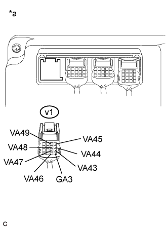
Text in Illustration *a Rear view of wire harness connector
(to Battery Smart Unit)
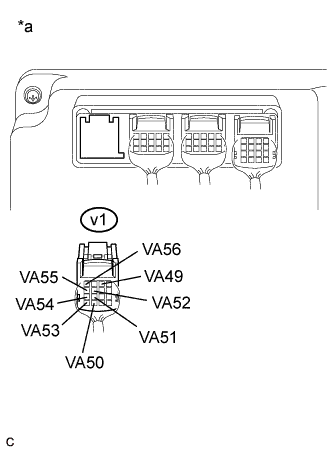
Text in Illustration *a Rear view of wire harness connector
(to Battery Smart Unit)
Measure the voltage according to the value(s) in the table below.
Standard Voltage (Battery Block 6) Tester Connection Condition Specified Condition v1-13 (GA3) - v1-9 (VA43) Power switch off 3.0 V or more v1-9 (VA43) - v1-5 (VA44) Power switch off 3.0 V or more v1-5 (VA44) - v1-1 (VA45) Power switch off 3.0 V or more v1-1 (VA45) - v1-14 (VA46) Power switch off 3.0 V or more v1-14 (VA46) - v1- 10 (VA47) Power switch off 3.0 V or more v1-10 (VA47) - v1-6 (VA48) Power switch off 3.0 V or more v1-6 (VA48) - v1-2 (VA49) Power switch off 3.0 V or more Standard Voltage (Battery Block 7) Tester Connection Condition Specified Condition v1-2 (VA49) - v1-15 (VA50) Power switch off 3.0 V or more v1-15 (VA50) - v1- 11 (VA51) Power switch off 3.0 V or more v1-11 (VA51) - v1-7 (VA52) Power switch off 3.0 V or more v1-7 (VA52) - v1-16 (VA53) Power switch off 3.0 V or more v1-16 (VA53) - v1- 12 (VA54) Power switch off 3.0 V or more v1-12 (VA54) - v1-8 (VA55) Power switch off 3.0 V or more v1-8 (VA55) - v1-4 (VA56) Power switch off 3.0 V or more Result Result Proceed to The difference between the highest and lowest value is less than 0.3 V and every measured value is 3.0 V or more. A Other than above. B Note
Make sure to check the polarity of each terminal (positive (+) or negative (-)) before connecting a tester.
-
Install the No. 1 hybrid vehicle battery shield panel.
-
-
2013/12 -:
-
Check that the service plug grip is not installed.
Note
After removing the service plug grip, do not turn the power switch on (READY), unless instructed by the repair manual because this may cause a malfunction.
-
Remove the No. 1 hybrid vehicle battery shield panel Click here.
-
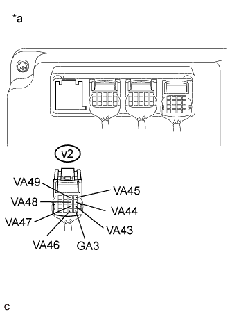
Text in Illustration *a Rear view of wire harness connector
(to Battery Smart Unit)

Text in Illustration *a Rear view of wire harness connector
(to Battery Smart Unit)
Measure the voltage according to the value(s) in the table below.
Standard Voltage (Battery Block 6) Tester Connection Condition Specified Condition v2-13 (GA3) - v2-9 (VA43) Power switch off 3.0 V or more v2-9 (VA43) - v2-5 (VA44) Power switch off 3.0 V or more v2-5 (VA44) - v2-1 (VA45) Power switch off 3.0 V or more v2-1 (VA45) - v2-14 (VA46) Power switch off 3.0 V or more v2-14 (VA46) - v2- 10 (VA47) Power switch off 3.0 V or more v2-10 (VA47) - v2-6 (VA48) Power switch off 3.0 V or more v2-6 (VA48) - v2-2 (VA49) Power switch off 3.0 V or more Standard Voltage (Battery Block 7) Tester Connection Condition Specified Condition v2-2 (VA49) - v2-15 (VA50) Power switch off 3.0 V or more v2-15 (VA50) - v2- 11 (VA51) Power switch off 3.0 V or more v2-11 (VA51) - v2-7 (VA52) Power switch off 3.0 V or more v2-7 (VA52) - v2-16 (VA53) Power switch off 3.0 V or more v2-16 (VA53) - v2- 12 (VA54) Power switch off 3.0 V or more v2-12 (VA54) - v2-8 (VA55) Power switch off 3.0 V or more v2-8 (VA55) - v2-4 (VA56) Power switch off 3.0 V or more Result Result Proceed to The difference between the highest and lowest value is less than 0.3 V and every measured value is 3.0 V or more. A Other than above. B Note
Make sure to check the polarity of each terminal (positive (+) or negative (-)) before connecting a tester.
-
Install the No. 1 hybrid vehicle battery shield panel.
-
B
REPLACE NO. 4 HYBRID VEHICLE SUPPLY STACK SUB-ASSEMBLY Click here
A
RETURNS TO NORMAL OPERATION
-